2FOC
Test Procedure
Revision history
| Rev. | Dep | Prepared by | Date | Revision description |
|---|---|---|---|---|
| 0 | EDL | A.Merello | 21/3/2012 | First Emission |
1 Document Scope
Info
This procedure shows how to test 2FOC electronic boards and applies to the following IIT code :
- 3336*, 2FOC, IIT - Electronic board with CAN interface, dual driver for brushless motors, power supply 18-48V, 20A full Band width, for iCub, new heatsink
2 Requirements
2.1 Hardware Requirements
- Any regulated 45V power supply with current regulation from 200mA to 2A with current reading.
- Digital multimeter 1% or better accuracy.
- 1-channel 100Mhz oscilloscope.
- 2FOC_ADC, IIT - Testing equipment for 2FOC boards (IIT-Cod.4569.D)
- CAN bus interface ESD USB-CAN (IIT-Cod.91)
- The 2FOC Test JIG and its cables and accessories (power supply cables, CAN cable, passive loads, etc)
- The cables and resistive loads for “out-of-jig” testing (test procedure phase 2).
- PICkit™ 4 In-Circuit Debugger/Programmer for Microchip PIC and dsPIC Flash Microcontrollers (IIT-Cod.16721)
2.2 Software Requirements
- The software package for 2FOC test
- A PC with at least two USB ports and Windows 10.
3 Test Procedure
Warning
Handle the test setup taking care to not break thin wires and connectors
3.1 Installing ETS test suite
Before any 2FOC board can be tested, the test software must be installed on the PC.
In order to do this, it is enough to run 2FOC ADC.exe and to follow the instructions that will be
shown on the screen.
During the installation the Microchip MPLAB IDE will be also installed.
Please do not change the default destination folder.
You can skip (cancel) the MPLAB installation if a recent MPLAB ( version >= 8.46 ) is installed in
the default destination folder on the PC.
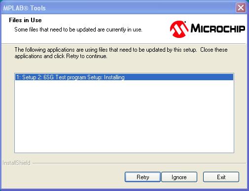
If the following screen appears during the installation of MPLAB, it is safe to click “ignore”
3.2 UI Brief Description
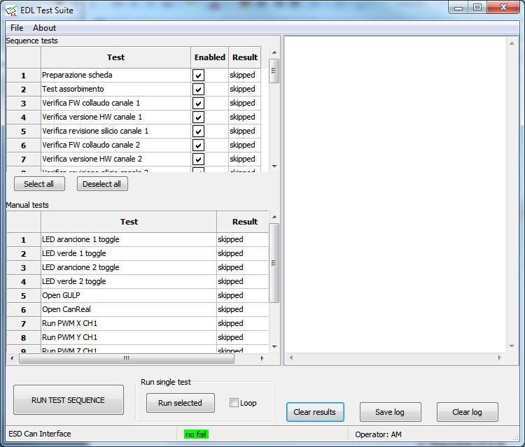
The EDL Test Suite UI is divided into four parts.
On the right a log box shows messages containing information about what is happening and which
operations have been performed.
-
The left part of the main window is divided into two sections. In the upper part the tests belonging to the normal test sequence are listed (they can be for example disabled or selected).
-
In the lower part the manual tests are listed. Those tests are not normally performed, but they can be useful to perform further investigation when something in the main test sequence goes wrong.
-
In the bottom part of the window there are some buttons that can be used to control the program: Clicking the button “RUN TEST SEQUENCE” will run the full test sequence. Once it is completed a report will be produced.
-
It is also possible to run single tests by selecting a test in the left part of the window and clicking the button “Run Selected”.
-
The “Loop” checkbox can be used to force the test to be repeated continuously. Doing this on tests that involves current flowing into the resistive loads can result in an excessive overheating of the resistive loads.
3.3 Test Procedure
The 2FOC test procedure is done in two phases.
Phase 1
It's performed with the aid of the test JIG, when the 2FOC board is fully assembled except for terminal blocks and MOSFETs. In this phase the MOSFETs on the test JIG are used in order to test the 2FOC board. Connection to these MOSFETs and to the power rail is achieved by some needles on the JIG. The JIG also contains passive loads (resistors) required to perform the tests. The bootloader and the test firmware are also programmed on the two microcontrollers using JTAG and CAN bus respectively. The JTAG interface is accessed by other smaller needles. When the test software is run, the phase 1 configuration file (default.xml) is automatically load.
Phase 1 tests brief description
• “preparazione scheda”: This is not really a test, but it describes all the operations required in order to prepare the DUT for testing (cables connection and insertion into the test JIG).
• “terminazione CAN”: This test is needed in order to check if the CAN bus termination resistors on the DUT are correctly installed (when required)
• “test assorbimento”: The DUT current consumption is checked to detect DUT power circuit major failures or DUT power lines shorts.
• “Test presenza 5V su connettori laterali”: This test is performed to check if the DUT is able to generate the required power on the external accessory connectors.
• “test MCLR”: This is the MCUs reset signal, it must be stable to ensure proper DUT operation.
• “test tensioni di alimentazione”: In this test all the DUT generated power supplies are checked for proper voltage.
• “test DC/DC 12V”: this is a more specific test for the DUT 12V internal power regulator
• “test DC/DC 5V”: this is a more specific test for the DUT 5V internal power regulator
• “test oscillatore”: the MCU clock signal electric parameters are checked.
• “Flash bootloader canale 2”: the JTAG operation for MCU #2 is checked and the bootloader is flashed in the internal MCU #2 memory
• “Flash bootloader canale 1”: the JTAG operation for MCU #1 is checked and the bootloader is flashed in the internal MCU #1 memory
• “FW CAN update canale 1”: the CAN bus operation for MCU #1 is checked and the test firmware is upload on the DUT memory
• “FW CAN update canale 2”: the CAN bus operation for MCU #2 is checked and the test firmware is upload on the DUT memory
• “Verifica FW collaudo canale 1”: This test verifies the presence and aliveness of the (correct version of) test firmware on MCU #1
• “Verifica FW collaudo canale 2”: This test verifies the presence and aliveness of the (correct version of) test firmware on MCU #2
• “Verifica versione HW canale 1”: The HW revision string reported by the MCU #1 is checked. Currently this value is hardcoded in the firmware. Hardware detection mechanisms are not implemented yet
• “Verifica versione HW canale 2”: The HW revision string reported by the MCU #2 is checked. Currently this value is hardcoded in the firmware. Hardware detection mechanisms are not implemented yet
• “Verifica revisione silicio canale 1”: The MCU #1 silicon revision is checked. Some old MCUs are not compatible with the application and they should not pass this test.
• “Verifica revisione silicio canale 2”: The MCU #2 silicon revision is checked. Some old MCUs are not compatible with the application and they should not pass this test.
• “test lettura ADC VDC 18V CH 1”: This tests the MCU #1 power rail ADC measurement with 18V power supply
• “test lettura ADC VDC 18V CH 2”: This tests the MCU #2 power rail ADC measurement with 18V power supply
• “test lettura ADC VDC 36V CH 1”: This tests the MCU #1 power rail ADC measurement with 36V power supply
• “test lettura ADC VDC 36V CH 2”: This tests the MCU #2 power rail ADC measurement with 36V power supply
• “TEST LED canale 1”: The two LEDs connected to MCU #1 operation is checked.
• “TEST LED canale 2”: The two LEDs connected to MCU #1 operation is checked.
• “TEST corto su segnali P1 CH1”: The external connector P1 is tested in order to detect shorts on its signals.
• “TEST corto su segnali P2 CH1”: The external connector P2 is tested in order to detect shorts on its signals.
• “TEST corto su segnali P6 CH2”: The external connector P6 is tested in order to detect shorts on its signals.
• “TEST corto su segnali P5 CH2”: The external connector P5 is tested in order to detect shorts on its signals.
• “TEST loop su segnali P1 CH1”: The external connector P1 is tested in order to ensure proper electric connection of its signals.
• “TEST loop su segnali P2 CH1”: The external connector P2 is tested in order to ensure proper electric connection of its signals.
• “TEST loop su segnali P6 CH2”: The external connector P6 is tested in order to ensure proper electric connection of its signals.
• “TEST loop su segnali P5 CH2”: The external connector P5 is tested in order to ensure proper electric connection of its signals.
• “test fault a riposo su CH1”: The MCU #1 overcurrent detection circuit output is verified when the current is not flowing on the loads
• “test fault a riposo su CH2”: The MCU #2 overcurrent detection circuit output is verified when the current is not flowing on the loads
• “test lettura ADC fase 1 CH1”:  the MCU #1 current reading circuit on motor phase 1 is checked.
• “test lettura ADC fase 2 CH1”: the MCU #1 current reading circuit on motor phase 2 is checked.
• “test lettura ADC fase 1 CH2”: the MCU #2 current reading circuit on motor phase 1 is checked.
• “test lettura ADC fase 2 CH2”: the MCU #2 current reading circuit on motor phase 2 is checked.
• “test pull-down PWM CH1”: the pull-down resistors presence on the PWM MCU #1 output signals is checked
• “test pull-down PWM CH2”: the pull-down resistors presence on the PWM MCU #2 output signals is checked
• “test short ponte CH 1 fase X”: This test detects if due to some malfunction one of the two MOSFETs on the X motor phase (MCU #1) is wrongly driven “closed”.
• “test short ponte CH 1 fase Y”: This test detects if due to some malfunction one of the two MOSFETs on the Y motor phase (MCU #1) is wrongly driven “closed”.
• “test short ponte CH 1 fase Z”: This test detects if due to some malfunction one of the two MOSFETs on the Z motor phase (MCU #1) is wrongly driven “closed”.
• “test short ponte CH 2 fase X”: This test detects if due to some malfunction one of the two MOSFETs on the X motor phase (MCU #2) is wrongly driven “closed”.
• “test short ponte CH 2 fase Y”: This test detects if due to some malfunction one of the two MOSFETs on the Y motor phase (MCU #2) is wrongly driven “closed”.
• “test short ponte CH 2 fase Z”: This test detects if due to some malfunction one of the two MOSFETs on the Z motor phase (MCU #2) is wrongly driven “closed”.
• “Test I su ponte CH1”: this test causes a certain amount of current to flow in the load through the MOSFETs, reads back the current measurement and verifies the value is in a reasonable range. This verifies the operation of mosfet driving circuit and current measurement circuit on MCU #1
• “Test I su ponte CH2”: this test causes a certain amount of current to flow in the load through the MOSFETs, reads back the current measurement and verifies the value is in a reasonable range. This verifies the operation of mosfet driving circuit and current measurement circuit on MCU #2.
• “Test protezione di corrente su CH 1”: This test causes an huge current to flow in the load for few microseconds and checks for the hardware current protection to detect it (MCU #1).
• “Test protezione di corrente su CH 2”: This test causes an huge current to flow in the load for few microseconds and checks for the hardware current protection to detect it (MCU #2).
• “fase 2 con componenti TH”: this is not really a test. It just remind the operator to perform the phase 2 test sequence once the through hole components (terminal blocks and mosfets) are assembled.
Phase 2
It's performed without the test JIG, when the 2FOC board is fully assembled including terminal blocks and MOSFETs. Power is supplied by using the 2FOC terminal block and two external resistive loads are connected to the motor phases terminal blocks. In order to perform phase 2 tests, it is required to load the “phase2.xml” configuration file in the test software. This can be easily done selecting “open” in the “file” menu. To revert back to the phase 1 test sequence the file “default.xml” should be loaded.
Phase 2 tests brief description
• “preparazione scheda”: This is not really a test, but it describes all the operations required in order to prepare the DUT for testing (cables connection)
•  “test assorbimento”: The DUT current consumption is checked to detect power circuit major failures or DUT power shorts.
• “Verifica FW collaudo canale 1”: This test verifies the presence and aliveness of (correct version of) test firmware on MCU #1
•  “Verifica versione HW canale 1”: The HW revision string reported by the MCU #1 is checked. Currently this value is hardcoded in the firmware. Hardware detection mechanisms are not implemented yet
• “Verifica revisione silicio canale 1”: The MCU #1 silicon revision is checked. Some old MCUs are not compatible with the application and they should not pass this test.
• “Verifica FW collaudo canale 2”: This test verifies the presence and aliveness of the (correct version of) test firmware on MCU #2
• “Verifica versione HW canale 2”: The HW revision string reported by the MCU #2 is checked. Currently this value is hardcoded in the firmware. Hardware detection mechanisms are not implemented yet
• “Verifica revisione silicio canale 2”: The MCU #2 silicon revision is checked. Some old MCUs are not compatible with the application and they should not pass this test.
• “Test fault a riposo su CH1”: The MCU #1 overcurrent detection circuit output is verified when the current is not flowing on the loads
• “Test lettura ADC fase 1 CH1”:  the MCU #1 current reading circuit on motor phase 1 is checked.
• “Test lettura ADC fase 2 CH1”: the MCU #1 current reading circuit on motor phase 2 is checked.
• “Test pull-down PWM CH1”: the pull-down resistors presence on the PWM MCU #1 output signals is checked
• “Test short ponte CH 1 fase X”: This test detects if due to some malfunction one of the two MOSFETs on the X motor phase (MCU #1) is wrongly driven “closed”.
• “Test short ponte CH 1 fase Y”: This test detects if due to some malfunction one of the two MOSFETs on the Y motor phase (MCU #1) is wrongly driven “closed”.
• “Test short ponte CH 1 fase Z”: This test detects if due to some malfunction one of the two MOSFETs on the Z motor phase (MCU #1) is wrongly driven “closed”.
• “Test I su ponte CH 1”: this test causes a certain amount of current to flow in the load through the MOSFETs, reads back the current measurement and verifies the value is in a reasonable range. This verifies the operation of mosfet driving circuit and current measurement circuit on MCU #1
• “Test fault a riposo su CH2”: The MCU #2 overcurrent detection circuit output is verified when the current is not flowing on the loads
• “Test lettura ADC fase 1 CH2”: the MCU #2 current reading circuit on motor phase 1 is checked.
• “Test lettura ADC fase 2 CH2”: the MCU #2 current reading circuit on motor phase 2 is checked.
•  “Test pull-down PWM CH2”: the pull-down resistors presence on the PWM MCU #2 output signals is checked
•  “Test short ponte CH 2 fase X”: This test detects if due to some malfunction one of the two MOSFETs on the X motor phase (MCU #2) is wrongly driven “closed”.
• “Test short ponte CH 2 fase Y”: This test detects if due to some malfunction one of the two MOSFETs on the Y motor phase (MCU #2) is wrongly driven “closed”.
• “Test short ponte CH 2 fase Z”: This test detects if due to some malfunction one of the two MOSFETs on the Z motor phase (MCU #2) is wrongly driven “closed”.
• “Test I su ponte CH 2”: this test causes a certain amount of current to flow in the load through the MOSFETs, reads back the current measurement and verifies the value is in a reasonable range. This verifies the operation of mosfet driving circuit and current measurement circuit on MCU #2
• “Test protezione di corrente su CH 1”: This test causes an huge current to flow in the load for few microseconds and checks for the hardware current protection to detect it (MCU #1).
• “Test protezione di corrente su CH 2”: This test causes an huge current to flow in the load for few microseconds and checks for the hardware current protection to detect it (MCU #2).
• “Update firmware repo”: This is not really a test, it updates the binaries of the bootloader and firmware using git.
• “FLASH bootloader canale 1”: This flashes the updtaed bootloader.
• “FLASH bootloader canale 2”: This flashes the updtaed bootloader.
• “FLASH firmware canale 1”: This flashes the updtaed firmware.
• “FLASH firmware canale 2”: This flashes the updtaed firmware.
• “Etichettatura”: This is not really a test, it is to remember to the operator to place the label on the DUT.