DC MOTORS
Test Procedure
Revision history
| Rev. | Dep | Prepared by | Date | Revision description |
|---|---|---|---|---|
| 0 | iCubFacility | D.Tomé | 11/12/2009 | First Emission |
| 1 | iCubFacility | D.Tomé | 22/03/2010 | Added indications and cable ties images |
| 2 | iCubFacility | D.Tomé | 19/07/2013 | Added Test Setup schematic |
| 3 | iCubFacility | D.Tomé | 12/09/2018 | Document aligned to new template; translated in English |
| 4 | icub-tech-iit | D.Tomé | 01/04/2020 | migrated to markdown |
1 Document Scope
Info
This procedure shows how to test brushed DC MOTORS and applies to the following IIT codes :
- 2694
- 12264
NOTE: May be necessary to add new IIT codes to IPTS suite
2 Requirements
2.1 Hardware Requirements
- 2 channels DC Power Supply (0-60V @20A) (fig.1-1)
- Digital Oscilloscope (fig.1-2)
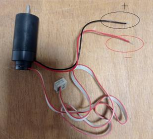
- DC motors test setup (fig.1-3)
- “TESTED” labels
- Cable ties (1.8x66mm or 2.5x100mm (depending by the motor to be tested)
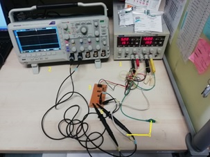
Figure 1 - Test Setup
2.2 Software Requirements
- PC with Windows 10
- IPTS test suite
3 Test Procedure
Warning
Handle the test setup taking care to not break thin wires and connectors
3.1 Installing IPTS test suite
- Double click on “IPTS-Setup.exe” and follow the wizard. This will install the test suite and other software required for the test (refer to the user manual for further information)
3.2 Test Procedure
- Run iCubProductionTestSuite.exe
- Follow the instructions given by the software

Figure 2 - IPTS GUI for DC MOTORS with encoder
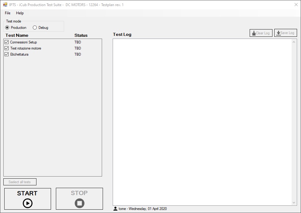
Figure 3 - IPTS GUI for encoderless DC MOTORS
3.3 Test Report
Info
Reach test reports by clicking File->Open TestReports folder… in the IPTS GUI.
Addendum : Test Setup Diagram
4 Test Procedure: neck motors
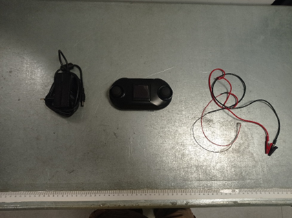
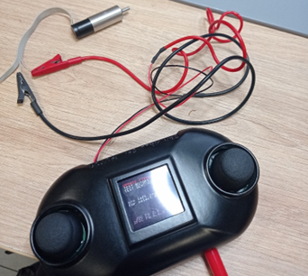
4.1 SET UP EQUIPMENT
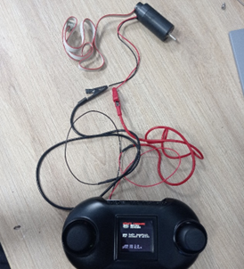
- Set-up jogger: jogger cod. 17005, power supply cod. 17020 and connector-terminal adapter
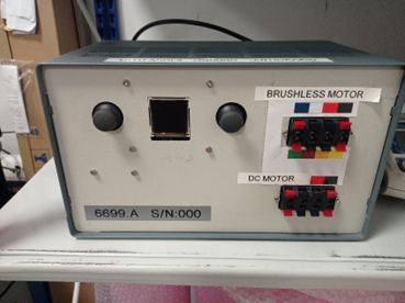
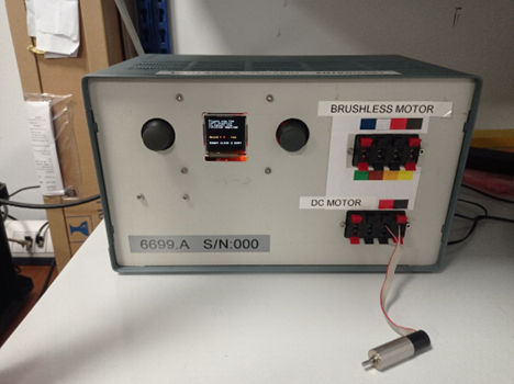
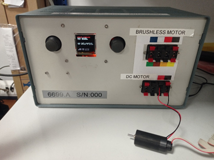
- Set-up jogger box : cod. 6699.A
| 1. Set-up jogger | 2. Set-up jogger box |
|---|---|
 |
 |
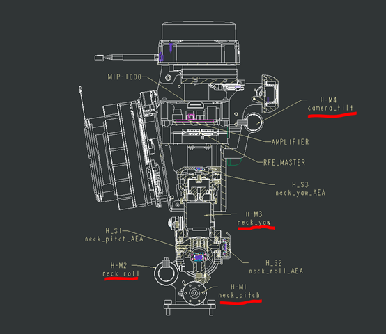
4.2 HEAD MOTOR
4.2.1 eCub 1.1 identification motor with relative voltage
| ID | Joint | Voltage | IIT code | Description |
|---|---|---|---|---|
| H-M1 | neck_pitch | 2.5v | 2714.1 | 2342S012CR+IE2-512+2082, Faulhaber - Brush motor, encoder with 500mm cable length |
| H-M2 | neck_roll | 2.5v | 2714.1 | 2342S012CR+IE2-512+2082, Faulhaber - Brush motor, encoder with 500mm cable length |
| H-M3 | neck_yaw | 1.8v | 2694 | 2224U012SR+IE2-512+2082 Faulhaber - Brush motor, encoder with 500mm cable lenght |
| H-M4 | camera_tilt | 1.5v | 2692 | 1524E012SR-IE2-512+15/8-141:1+2082 Faulhaber - Brush motor, encoder with 500mm cable lenght |
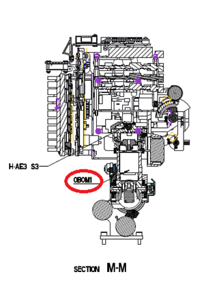
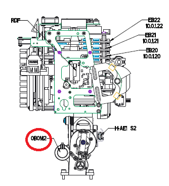
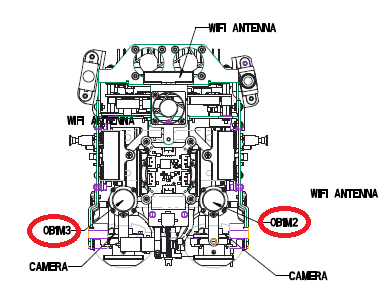
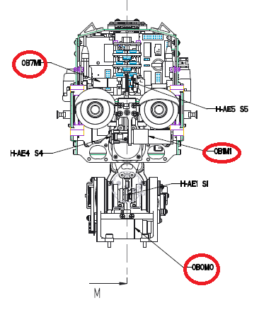
4.2.2 iCub 2.7 identification motor with relative voltage
| ID | Joint | Voltage | IIT code | Description |
|---|---|---|---|---|
| 0B0M0 | neck_pitch | 2.5v | 2714.1 | 2342S012CR+IE2-512+2082, Faulhaber - Brush motor, encoder with 500mm cable length |
| 0B0M2 | neck_roll | 2.5v | 2714.1 | 2342S012CR+IE2-512+2082, Faulhaber - Brush motor, encoder with 500mm cable length |
| 0B0M1 | neck_yaw | 1.8v | 2694 | 2224U012SR+IE2-512+2082 Faulhaber - Brush motor, encoder with 500mm cable lenght |
| 0B1M1 | camera_tilt | 1.5v | 12264 | FAULHABER MOTOR 1016M012GK380+GEARBOX 10/1 i=16 |
| 0B1M2 | eye_pan_motor | 7v | 2693 | 1717T012SR+IE2-512+2082, Faulhaber - Brush motor, encoder with 500mm cable lenght |
| 0B1M2 | eye_pan_motor | 7v | 2693 | 1717T012SR+IE2-512+2082, Faulhaber - Brush motor, encoder with 500mm cable lenght |
 |
 |
 |
 |
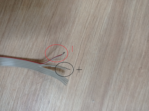
4.3 HOW CONNECT THE MOTOR AT THE SET-UP
- For connect dc motor cod. 2694, cod 12264, cod. 2693, cod. 2693, cod. 2692. To test these specific motors it is necessary to strip the first two cables of the flat which correspond to the two poles. Then connect the two poles to the set-up used jogger or joggerbox
 |
 |
 |
- For direct current motor code 2714.1 the cables of the two poles are the larger ones, one red and one black. Connect these two to the set-up
 |
 |
 |
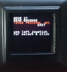
4.4 MOVE THE MOTOR
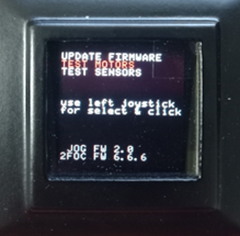
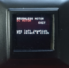
- Select the test motor function on the display,
- select dc motor option
- and using the tese proxima function.
| 1 | 2 | 3 |
|---|---|---|
 |
 |
 |
Note
Bringing the motor to the specific voltage indicated in the table, note on the test report how many starts to move. All fields indicated in the test report must be completed: TestReport.Collaudo.motori.dc.xlsx