FAP5
Test Procedure
1 Document Scope
Info
This procedure shows how to test FAP5 electronic boards and applies to the following IIT code :
- 15423.A FAP5, IIT - FingerAbsolutePosition_5_fingers
2 Requirements
2.1 Hardware Requirements
- ESD USB-CAN with usb power supply cable. [cod.IIT 1014]
- ST-Link debugger [cod.IIT 1349]
- RFE_MASTER golden board [cod.IIT 12024.C] + test cable set [to be coded]
2.2 Software Requirements
- PC with Windows 10
- IPTS test suite
3 Test Procedure
Warning
Handle the test setup taking care to not break thin wires and connectors
3.1 Installing IPTS test suite
- Double click on “IPTS-Setup.exe” and follow the wizard. This will install the test suite and other software required for the test (refer to the user manual for further information)
3.2 Setup Connections
-
Connect the setup referring to Fig.1
-
Connect the ST-LINK's debugger (1) to the J8 RFE's connector (2) an to the PC
- Connect the USB/CAN's interface (3) to the J4 RFE's connector (4) and to the PC
- Connect the FAP5 (5) to be tested to J10 rfe connector (6)
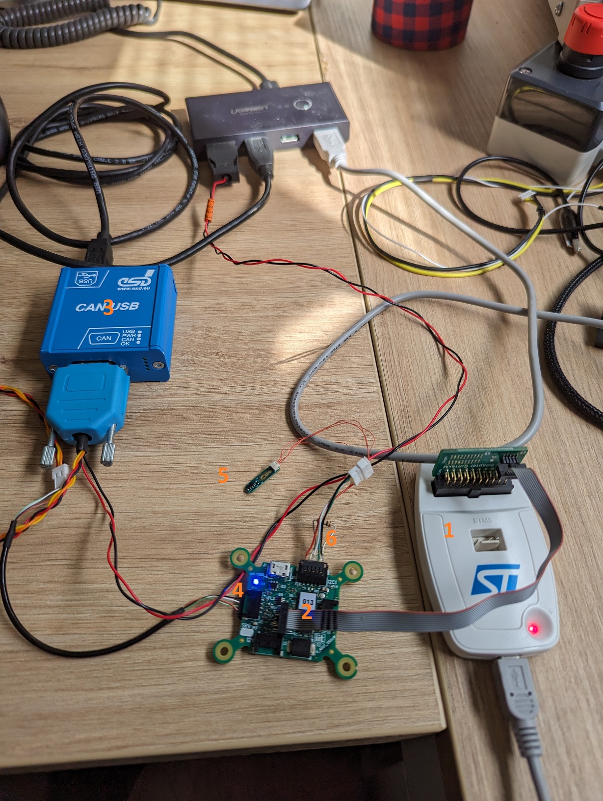
Figure 1 - Test Setup
3.3 Test Procedure
- Run iCubProductionTestSuite.exe with Administrator privileges
- Follow the instructions given by the software
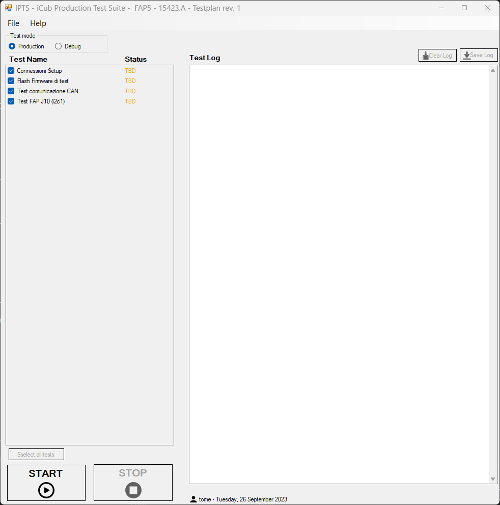
Figure 2 - IPTS GUI for FAP5 testing
3.4 Test Report
Info
Reach test reports by clicking File->Open TestReports folder… in the IPTS GUI.