BLDC MOTORS
Test Procedure
Revision history
| Rev. | Dep | Prepared by | Date | Revision description |
|---|---|---|---|---|
| 0 | icub-tech-iit | G.Vassallo | 19/09/2023 | First emission |
1 Test Procedure: eCub upperbody brushless motors
1.1 SET UP EQUIPMENT
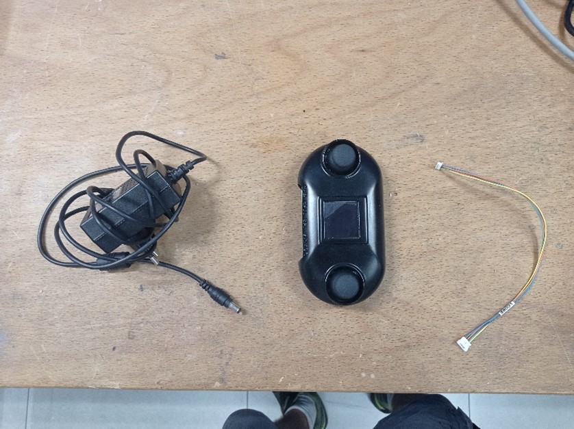
- Set-up jogger: jogger cod. 17005, power supply cod. 17020 and connector-terminal adapter
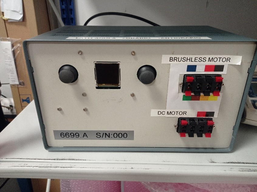
- Set-up jogger box : cod. 6699.A
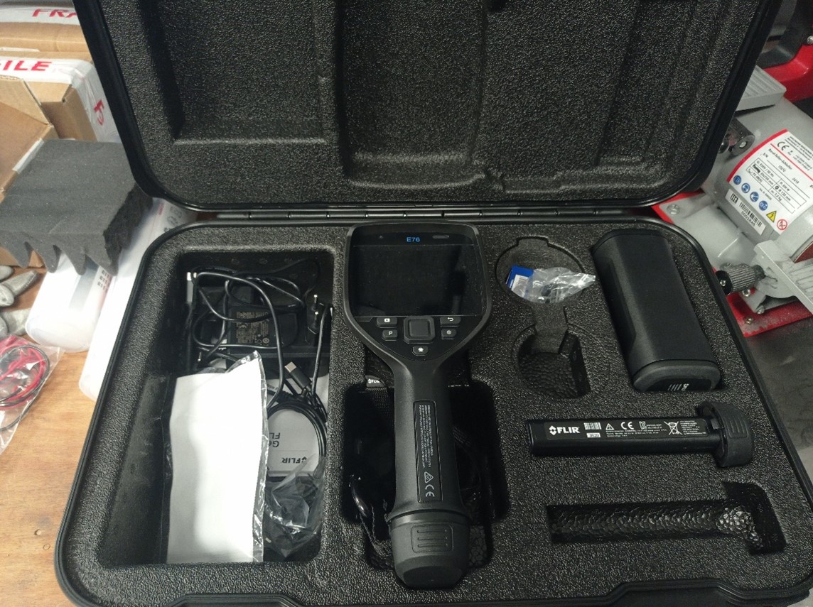
- Set-up termal imaging camera
| 1. Set-up jogger | 2. Set-up jogger box | 3. Set-up termal imaging camera |
|---|---|---|
 |
 |
 |
1.2 UPPERBODY MOTOR
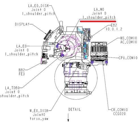
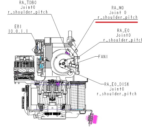
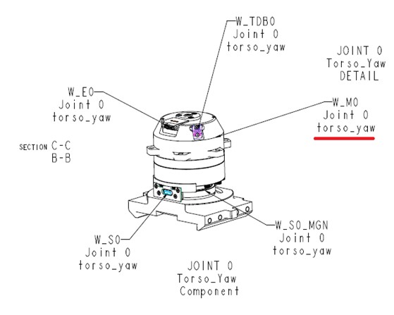
1.2.1 eCub 1.1 identification motor of chest with relative voltage
| ID | Joint | Voltage | IIT code | Description | Harmonic (IITcode) |
|---|---|---|---|---|---|
| LA-M0 | l_shoulder_pitch | 2.5v | 7117 | Moog BLDC motor, OD 49.2, ID 15.5, L 24.7 , W/O HALL SENSOR | 6729 |
| RA_M0 | r_shoulder_pitch | 2.5v | 7117 | Moog BLDC motor, OD 49.2, ID 15.5, L 24.7 , W/O HALL SENSOR | 6729 |
| W-M0 | torso_yaw | 2.5v | 7117 | Moog BLDC motor, OD 49.2, ID 15.5, L 24.7 , W/O HALL SENSOR | 6729 |
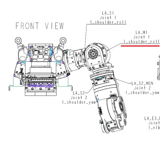
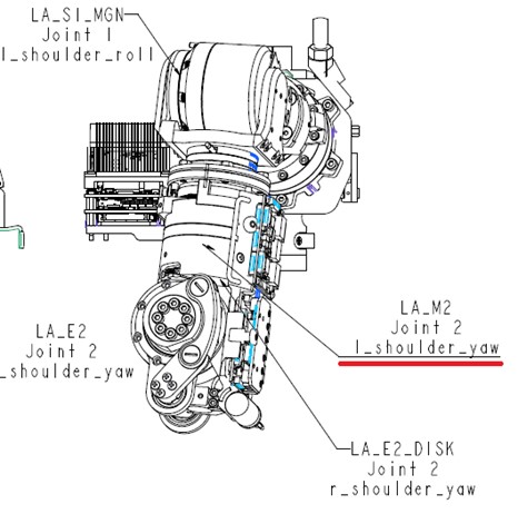
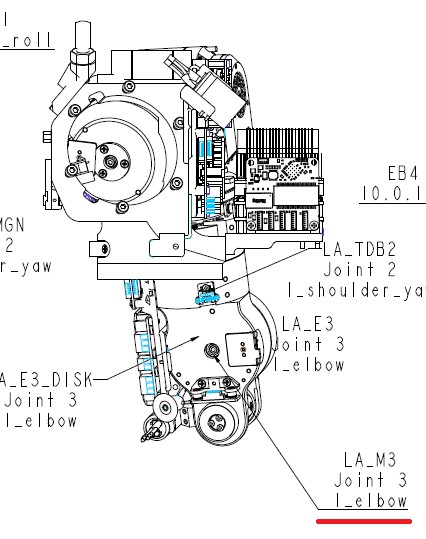
1.2.2 eCub 1.1 identification motor of left upperarm with relative voltage
| ID | Joint | Voltage | IIT code | Description | Harmonic (IITcode) |
|---|---|---|---|---|---|
| LA_M1 | l_shoulder_roll | 2.5v | 7117 | Moog BLDC motor, OD 49.2, ID 15.5, L 24.7 , W/O HALL SENSOR | 15483 |
| LA_M2 | l_shoulder_yaw | 2.5v | 7116 | Moog BLDC motor, OD 49.2, ID 15.5, L 17.7 , W/O HALL SENSOR | 6727 |
| LA_M3 | l_elbow | 2.5v | 7116 | Moog BLDC motor, OD 49.2, ID 15.5, L 17.7 , W/O HALL SENSOR | 15483 |
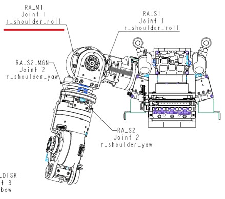
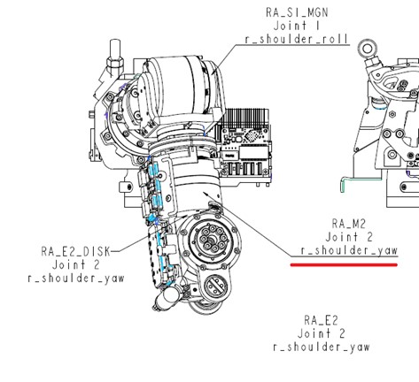
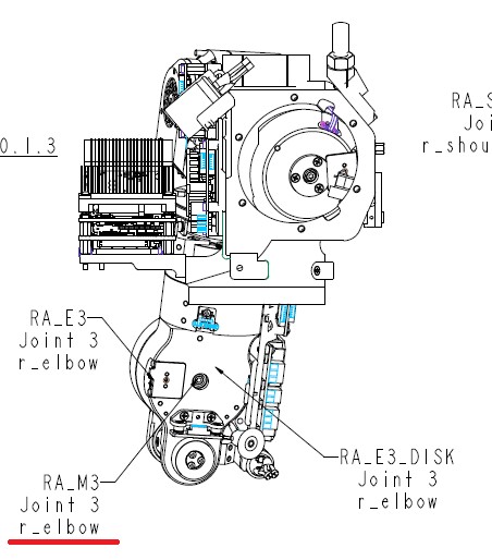
1.2.3 eCub 1.1 identification motor of right upperarm with relative voltage
| ID | Joint | Voltage | IIT code | Description | Harmonic (IITcode) |
|---|---|---|---|---|---|
| RA_M1 | r_shoulder_roll | 2.5v | 7117 | Moog BLDC motor, OD 49.2, ID 15.5, L 24.7 , W/O HALL SENSOR | 15483 |
| RA_M2 | r_shoulder_yaw | 2.5v | 7116 | Moog BLDC motor, OD 49.2, ID 15.5, L 17.7 , W/O HALL SENSOR | 6727 |
| RA_M3 | r_elbow | 2.5v | 7116 | Moog BLDC motor, OD 49.2, ID 15.5, L 17.7 , W/O HALL SENSOR | 15483 |
1.3 HOW CONNECT THE MOTOR AT THE SET-UP
• For all upperbody motors cod 7117 and cod. 7116 the cables to connect to the jogger box are the three longest and thickest red white and black cables highlighted in the photo.
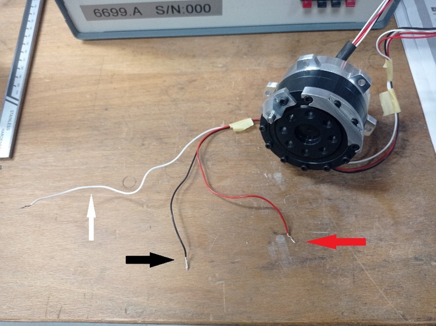
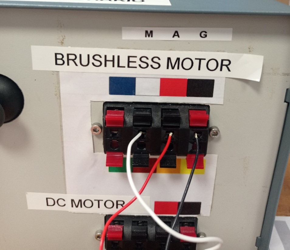
• The cables must be connected to the jogger box to the corresponding colored terminals in the part dedicated to the brushless ones
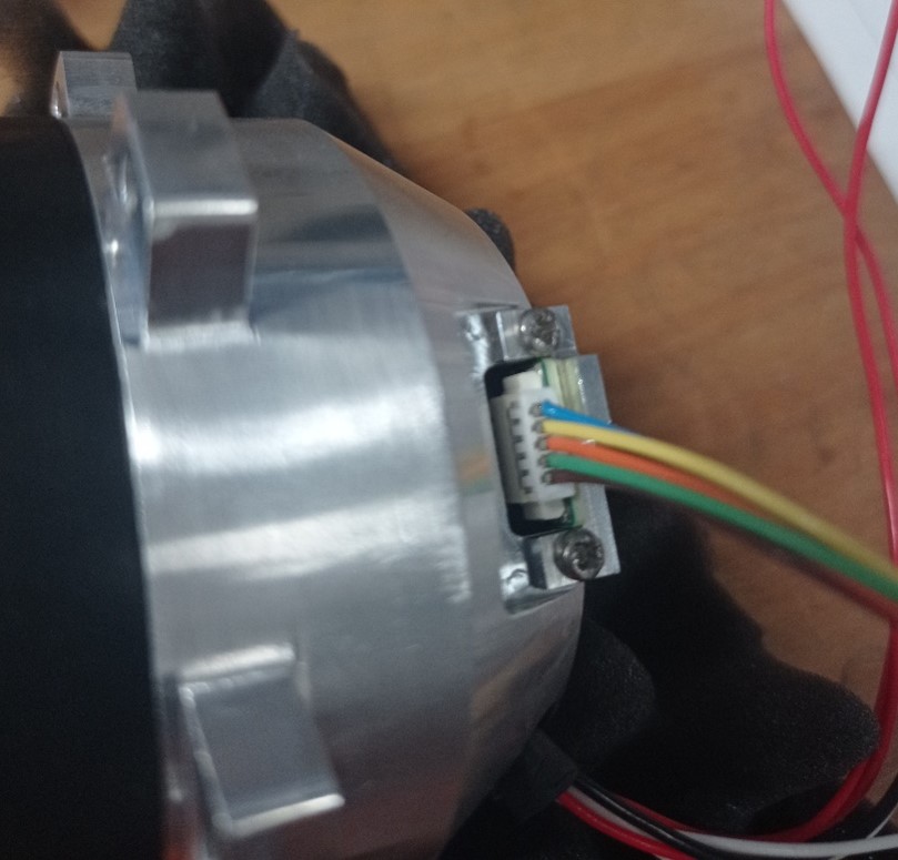
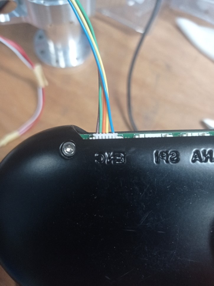
• Connect the Lcore board to yogger set-up. Use the adapter to connect the ENC output of the yogger to the output of the board.
1.4 MOVE THE MOTOR AND TEST THE LCORE
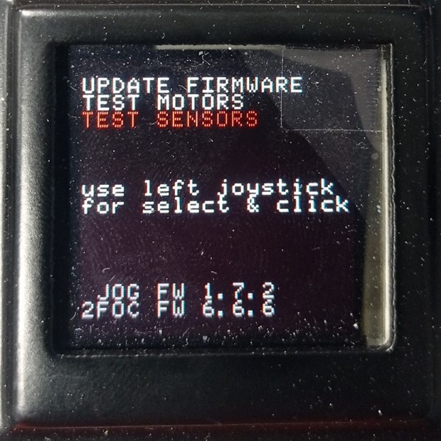
• Once the motor unit has been connected, you can proceed with the test. Before starting the motor, you must activate the optical disc reading function. Follow the directions in the photo.
- Select the test sensor function.
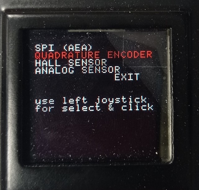
- Select the quadrature encoder.
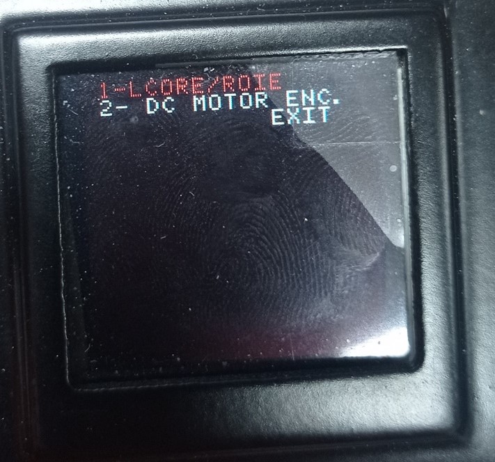
- Select the first function : Lcore/rote
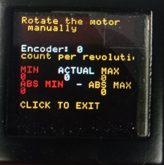
- Last function is selected, the disc reading screen will appear
| 1 | 2 | 3 | 4 |
|---|---|---|---|
 |
 |
 |
 |
• At this point you need to start the engine.
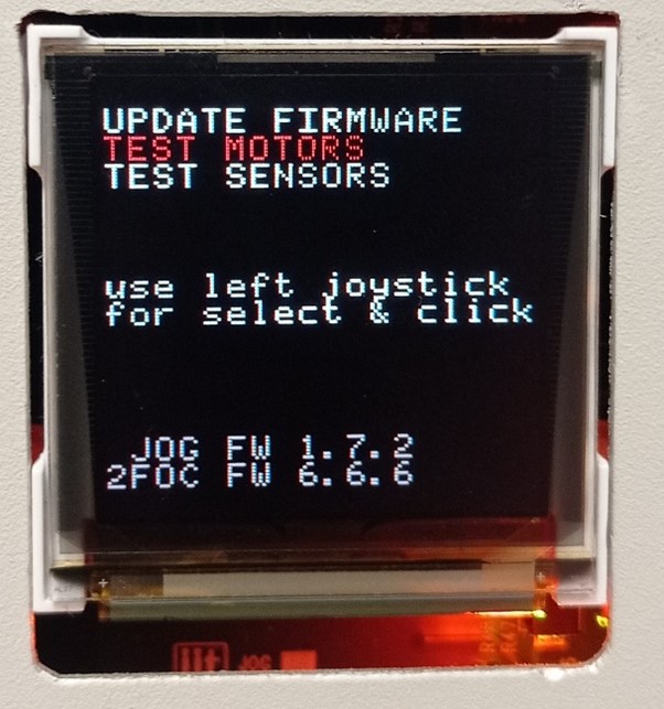
- In the display of the yogger box you must select test motors
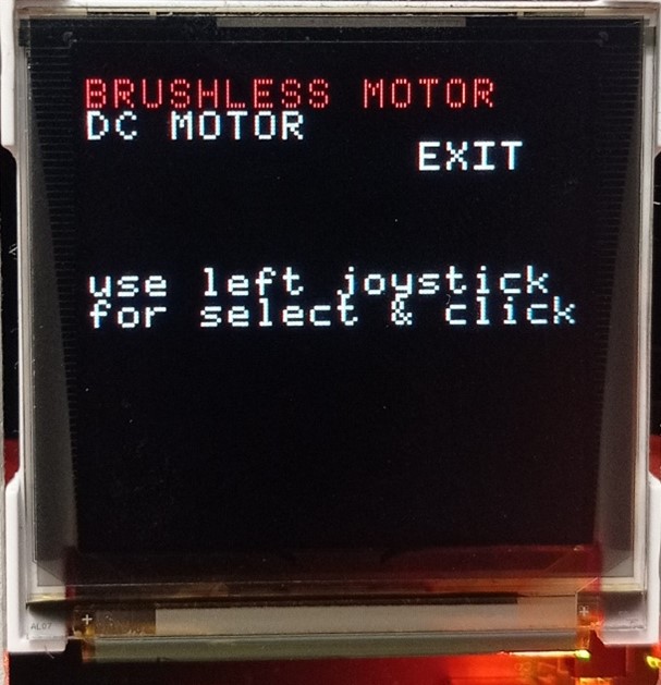
- Select brushless motor
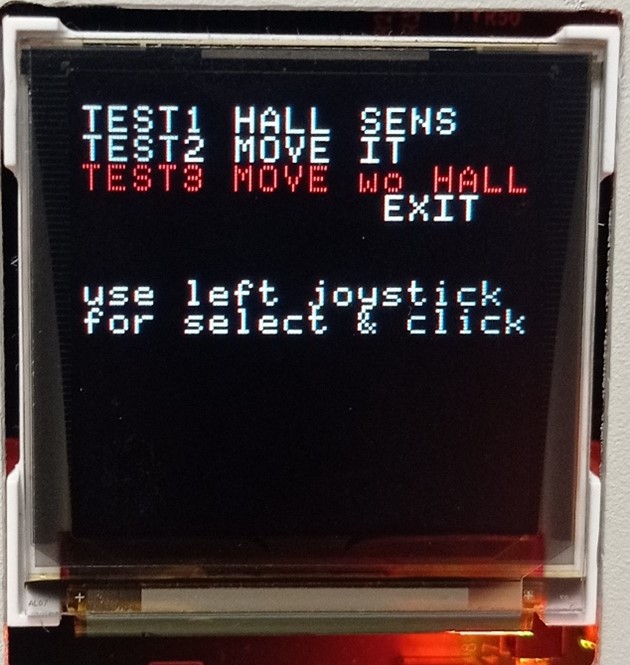
- Select Test3 move wo Hall
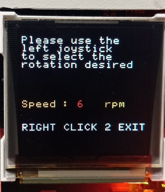
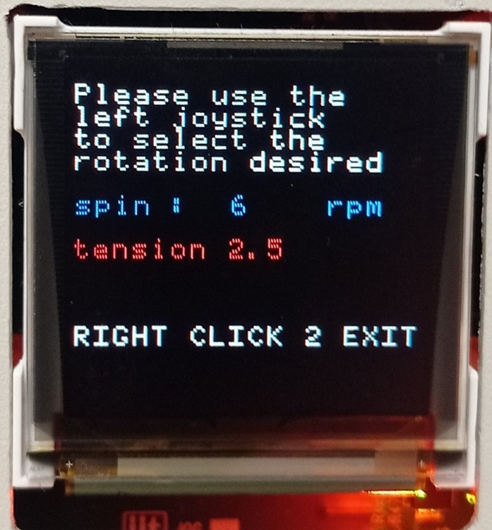
- Setting the speed at -6rpm (clockwise for 15 minutes) +6rm (countercolokwisefor 15 minutes)
- Bring to voltage 2,5V
| 1 | 2 | 3 | 4 | 5 |
|---|---|---|---|---|
 |
 |
 |
 |
 |
• Run the engine in by rotating it for 15 minutes in each direction
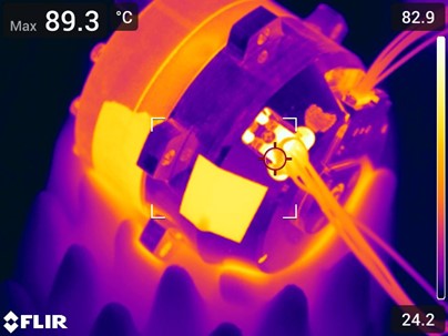
1.5 TEMPERATURE DETECTION
• After the engine has run for 15 minutes in each direction, the temperature can be measured using the thermal imaging camera. Direct the pointer towards the opening for the stator case sensor so as to take the internal temperature of the group. Take a photo of it which will be included in the test report attached at the end of the procedure.
1.6 GENERATE TEST REPORT
• After having carried out all the steps set out in the procedure, fill in the test report with the requested data.
Note
Bringing the motor to the specific voltage indicated in the table, note on the test report how many starts to move. All fields indicated in the test report must be completed: TestReport.Collaudo.motori.bldc.xlsx