DISPLAY 4D SYSTEMS - uOLED
Revision history
| Rev. | Dep | Prepared by | Date | Revision description |
|---|---|---|---|---|
| 0 | icub-tech-iit | A. Mura | 31/12/2020 | First Emission |
| 1 | icub-tech-iit | iCub Doctor | 05/01/2021 | add display initialization for JOG Board |
| 2 | icub-tech-iit | V. Del Bono | 15/04/2021 | added programming procedure for JOG Board |
| 3 | icub-tech-iit | M. Maggiali | 04/01/2023 | updated programming procedure for JOG Board |
Display use onto R1 and iCub3 robot
HW Requirements:
- 4D Systems
uOLED-128-G2display (IITCODE 7282) - uSD card SPI supported (IITCODE 15022)
- 4D Systems
uUSB-PA5-IIUSB to Serial-TTL UART bridge converter (IITCODE 15065) (or equivalent) - mini USB cable
SW requirements:
- Download and install 4D Systems
Workshop4from this link.
STEP by STEP guide
Important: use only uSD cards SPI supported, for more information see this issue.
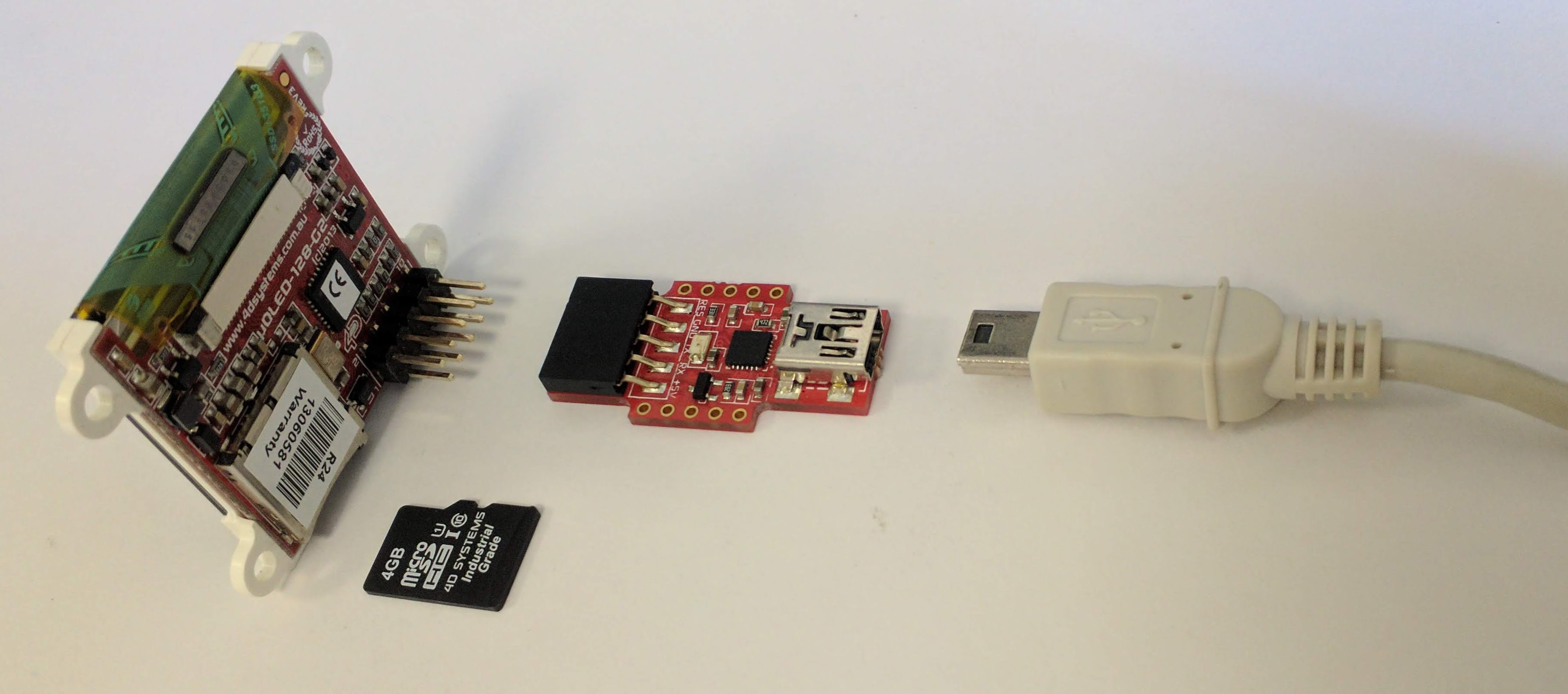
Connect the components:
Choose the project you are interested in at this link and open the related .4DViSi project:
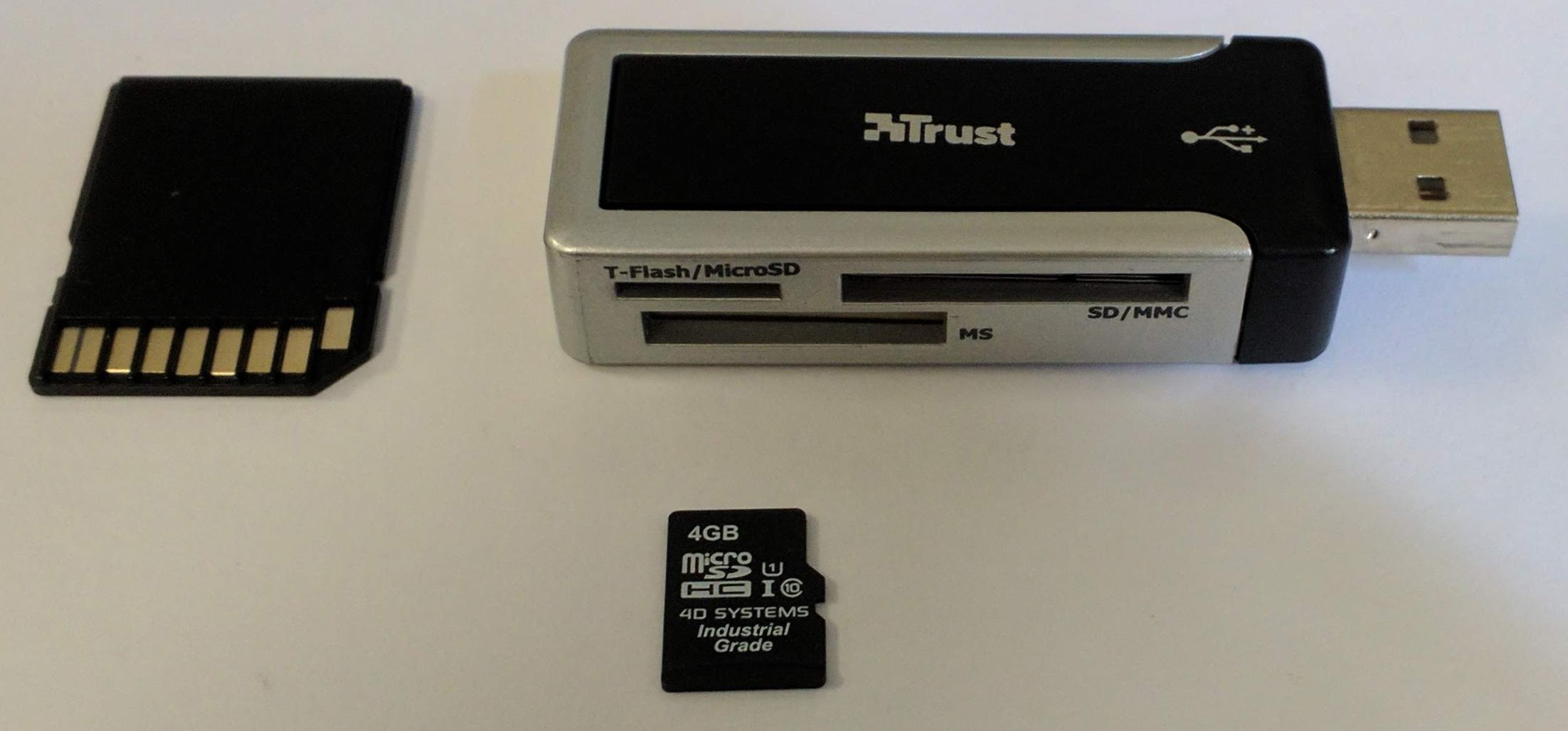
Connect the uSD to the PC with an adapter, for example:
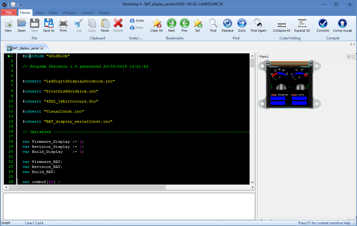
Program the display by clicking on Comp'nLoad:

During the programming process, a window appears:
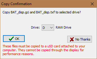
Select the drive and click on ✔️OK.
Note: if the previous window doesn't appear, no modifications on the graphics are seen by the software; the workaround is to select an element and change a property, e.g. the offset, and then replace the value and save. This way, the software sees a change and during Comp'nLoad it opens the window for the copy on the micro SD.
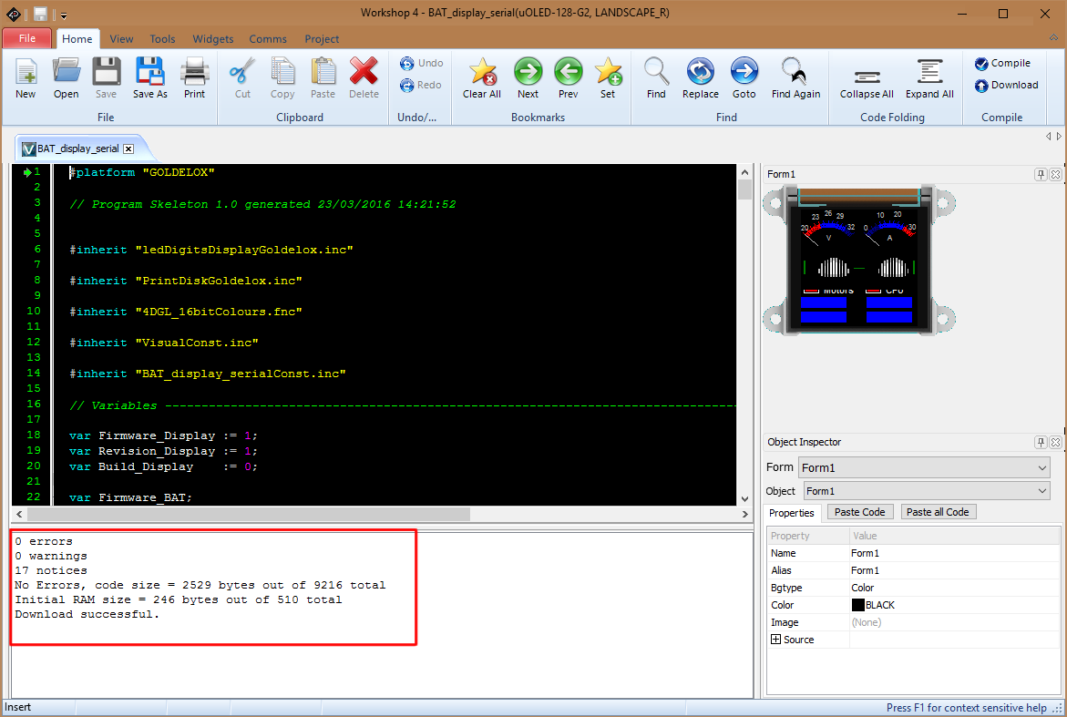
After a while messages appear in the output window and the display is programmed:
Display use on JOG Board
HW Requirements:
- 4D Systems
uOLED-128-G2display (IITCODE 7282) - 4D Systems
uUSB-PA5-IIUSB to Serial-TTL UART bridge converter (IITCODE 15065) + (or equivalent 4D programming cable) - mini USB cable (if using uUSB-PA5-II)
SW requirements:
- Download and install 4D Systems
Workshop4from this link.
STEP-by-STEP guide
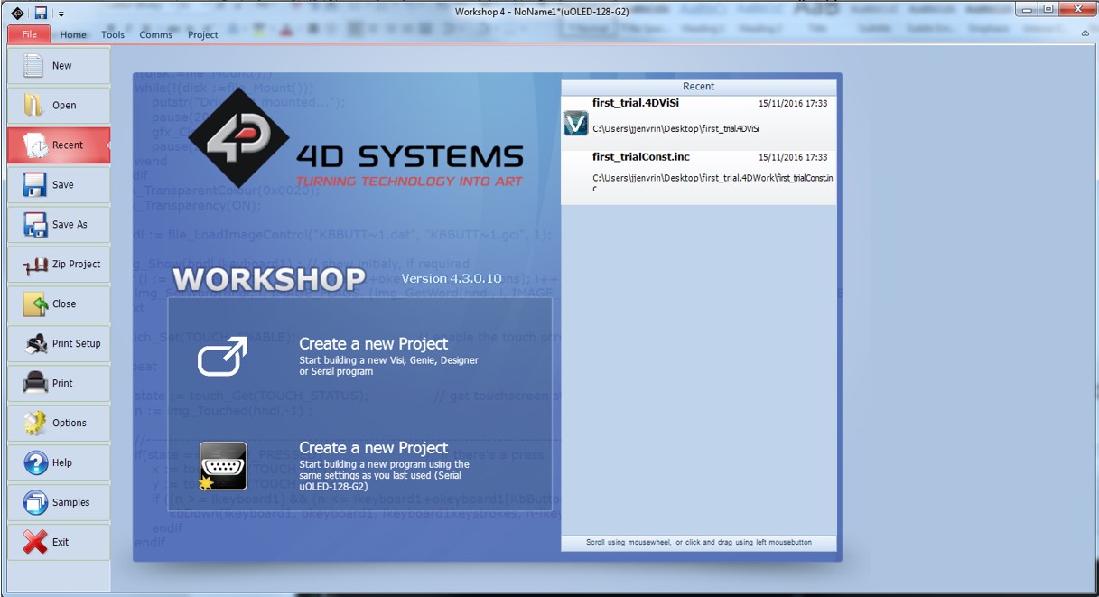
- Launch the
Workshop4main application
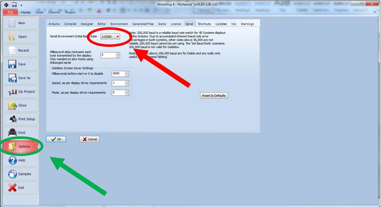
- Click on
Optionson the left side toolbar and set the baud rate to 115200Hz
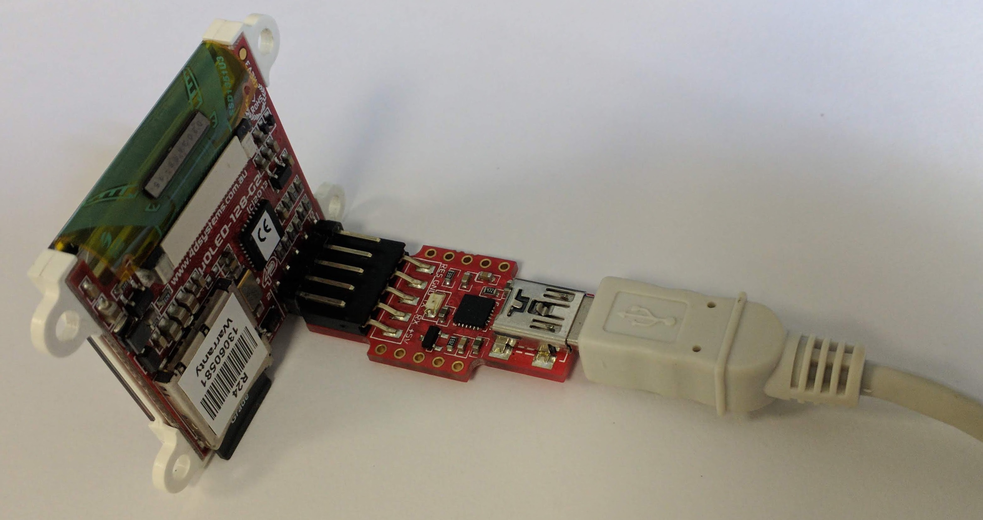
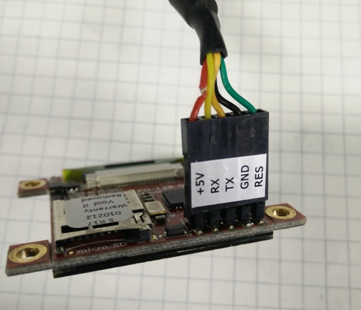
- Connect the screen to the laptop via the use of the
uUSB-PA5-II + USB extensionor the 4D programming cable as per the photo below
 Please, note that no uSD card is inserted in this process
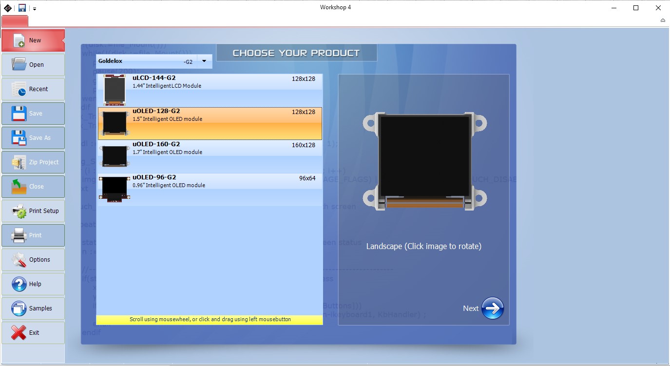
- Create a new Project and select the
uOLED-128-G2
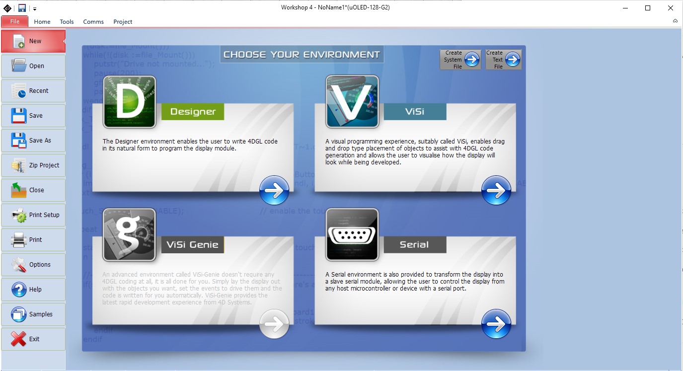
- Choose the
SerialProgramming icon
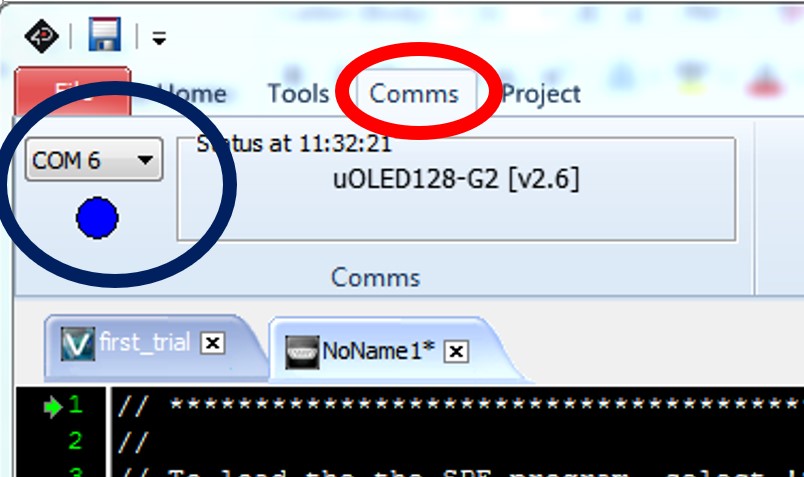
- Click on the tab
Comms- At this point, if everything goes smoothly the device should identify and a blue circle as well as a COM port on which the device is attached should be displayed.
- Click on the tab
Tools
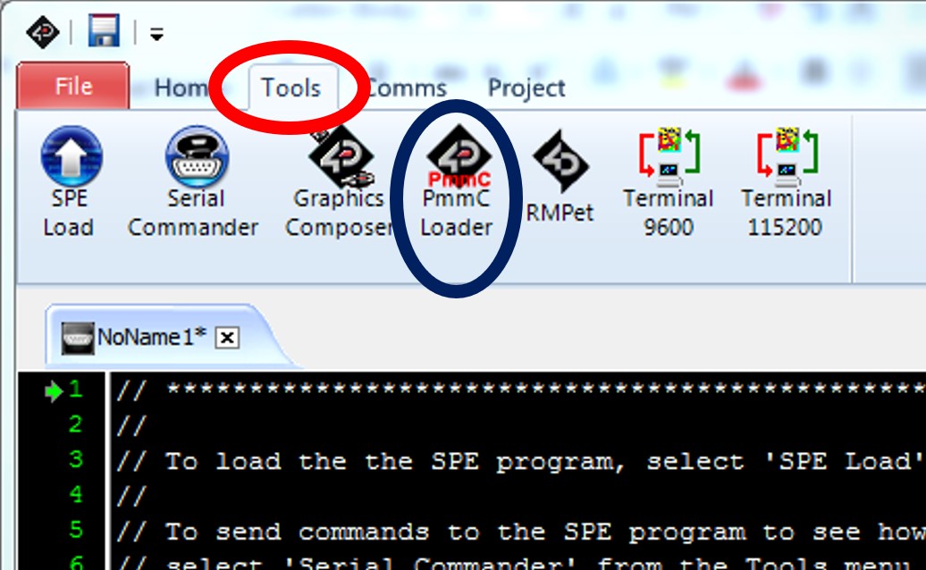
- Click onto the button
Pmmc Loader, a new window should pop-up
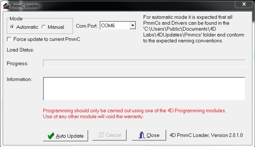
- Click on Auto-Update
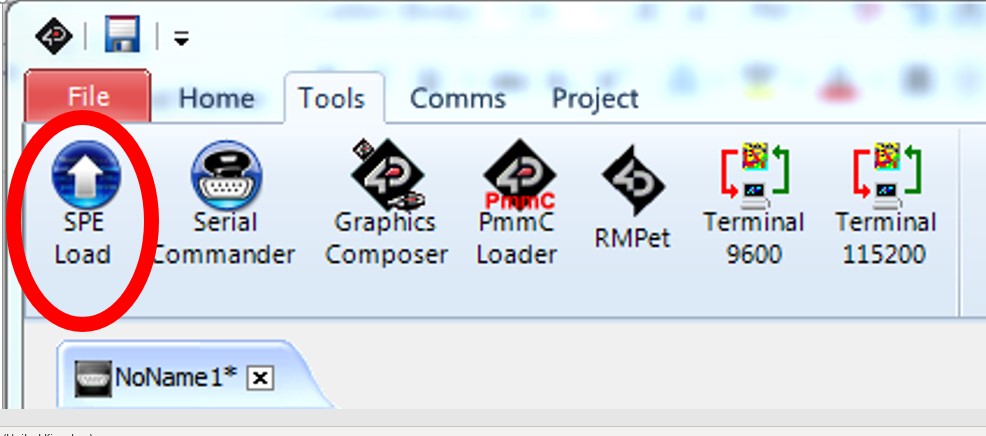
- Last but not least, click on
SPE Load
If everything goes well the screen should look like this
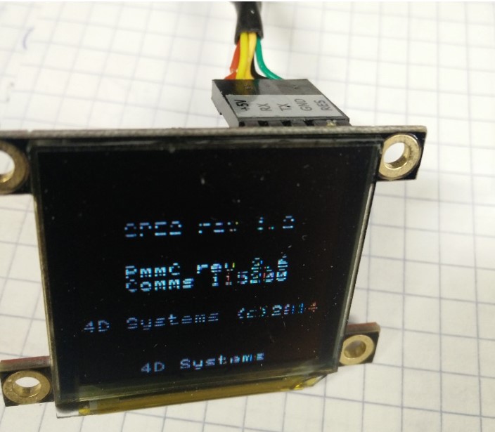
Pmmc rev number and the Comms 115200Hz should be displayed
END