STRAIN2
Test Procedure
Revision history
| Rev. | Dep | Prepared by | Date | Revision description |
|---|---|---|---|---|
| 0 | iCubFacility | D.Tomé | 09/07/2018 | First Emission |
| 1 | icub-tech-iit | D.Tomé | 31/03/2020 | migrated to markdown |
1 Document Scope
Info
This procedure shows how to test STRAIN2 electronic boards and applies to the following IIT code :
- 11996.B STRAIN2, IIT - Electronic board, 6 channels strain gauges variable gain interface board with CAN/UART, Temperature sensor, IMU, STM32L4
- 11996.C STRAIN2, IIT - Electronic board, 6 channels strain gauges variable gain interface board with CAN/UART, Temperature sensor, IMU, STM32L4
2 Requirements
2.1 Hardware Requirements
- ESD USB-CAN with usb power supply cable. (Fig.1 –> 2) [cod.IIT 1014]
- STRAIN2_ADC Test equipment (Fig.1 –> 4) [cod.IIT 12465]
- ST-Link debugger (Fig.1 –> 3) [cod.IIT 13499]
2.2 Software Requirements
- PC with Windows 10
- IPTS test suite
3 Test Procedure
Warning
Handle the test setup taking care to not break thin wires and connectors
3.1 Installing IPTS test suite
- Double click on “IPTS-Setup.exe” and follow the wizard. This will install the test suite and other software required for the test (refer to the user manual for further information)
3.2 Setup Connections
-
Connect the setup referring to Fig.1
-
Connect ESD CAN-USB (2) and ST-Link (3) to the PC’s USB (1)
- Connect ESD CAN-USB (2) to the STRAIN2_ADC (4)
- Connect ST-Link (3) to the STRAIN2_ADC (4)
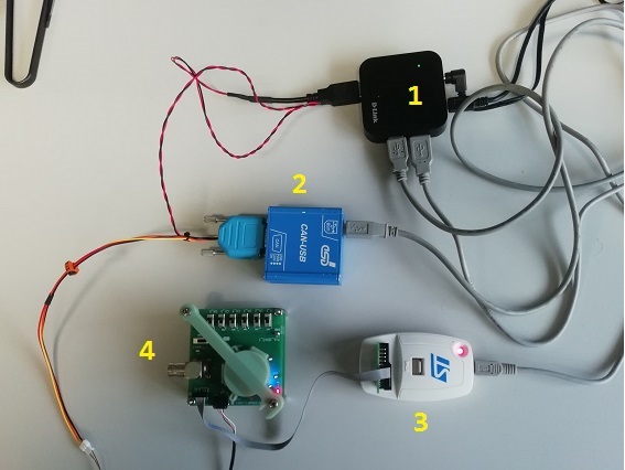
Figure 1 - Test Setup
3.3 Test Procedure
- Run iCubProductionTestSuite.exe with Administrator privileges
- Follow the instructions given by the software
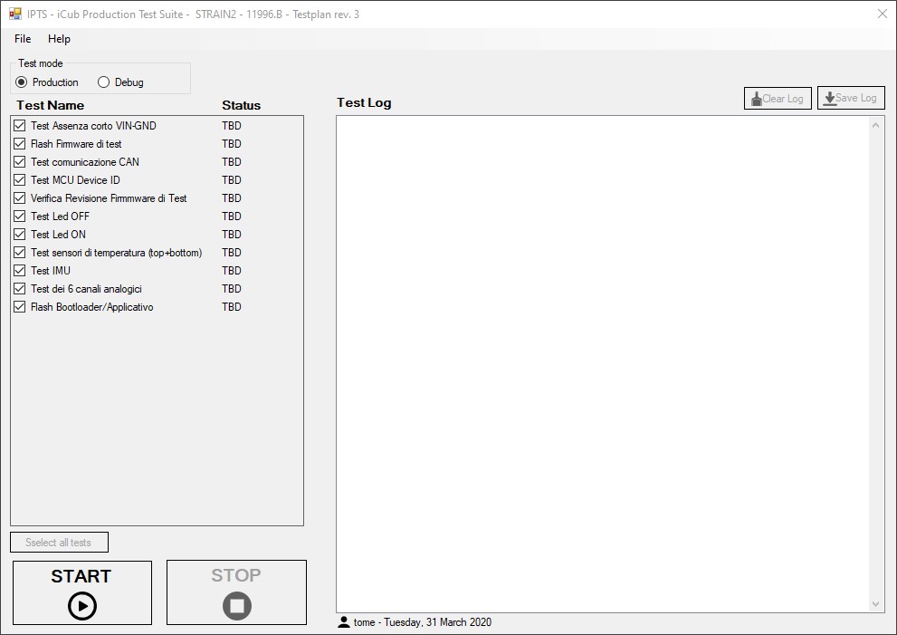
Figure 2 - IPTS GUI for STRAIN2 testing
3.4 Test Report
Info
Reach test reports by clicking File->Open TestReports folder… in the IPTS GUI.