MAIS
1 Document Scope
Info
This procedure shows how to test MAIS electronic boards and applies to the following IIT code :
- 1745.D MAISR (right hand), IIT - Electronic board, 32-channel miniature ADC card, without protection for inverted power polarity (With extended power range)
- 1746.D MAISL (left hand), IIT - Electronic board, 32-channel miniature ADC card, without protection for inverted power (With extended power range)
2 Requirements
2.1 Hardware Requirements
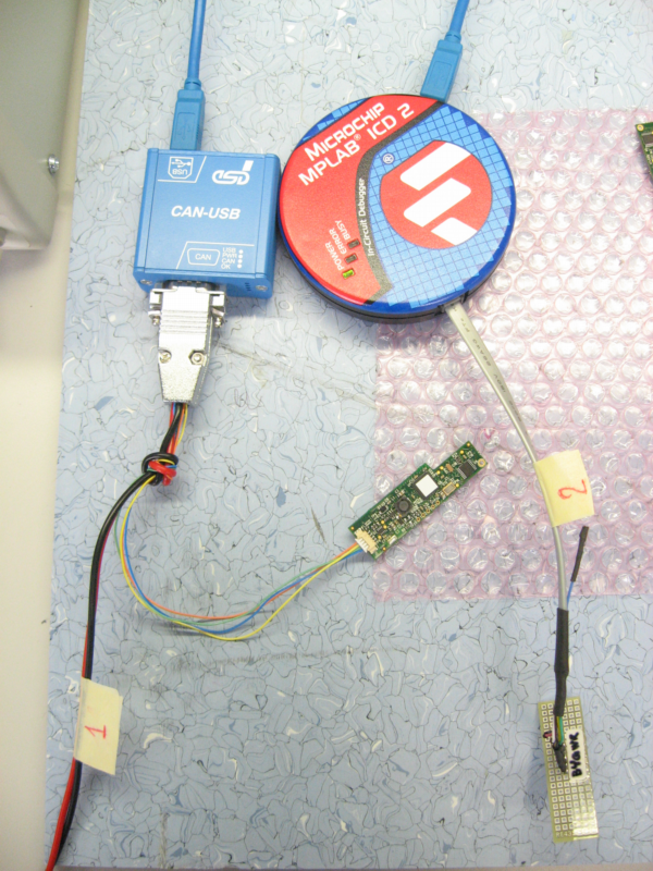
- ESD USB-CAN with usb power supply cable. [cod.IIT 1014]
- In-circuit debugging device Microchip ® MPLAB ICD2
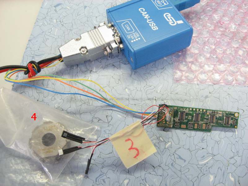
- Magnet (4)
- ESD-USB CAN with USB power supply cable (1)
- Programming cable (2)
- Hall sensors board (3)
- Capacitor array, 4x100nF, 16V, 20%, X7R, SMD, 1206
2.2 Software Requirements
-
Windows 10 :
- MPLAB IDE v8.50
- GULP software tool [© Istituro Italiano di Tecnologia]
- ESD CAN-USB SDK and drivers [© esd electronics gmbh]
-
Ubultu 20.04 LTS :
- robotology-superbuild installed
3 Visual Check
Check if the mais board has some damages or aseembly/soldering problems
4 Connections
- Connect both ESD USB-CAN and ICD3 to the Windows 10 machine
- Connect the programming cable (2) to the ICD2 debugger
5 Bototloader install
- Download and extract this archive
- Run
MPLAB IDE File->Open Workspaceand select theAdCStrain.mcwworkspace inside the above folderFile->Import...and selectBootloader.hex
- Place the nails of the programming cable (2) as in the picture below taking care to keep it until the ptogramming is not ended.
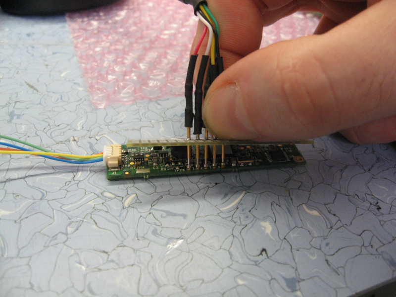
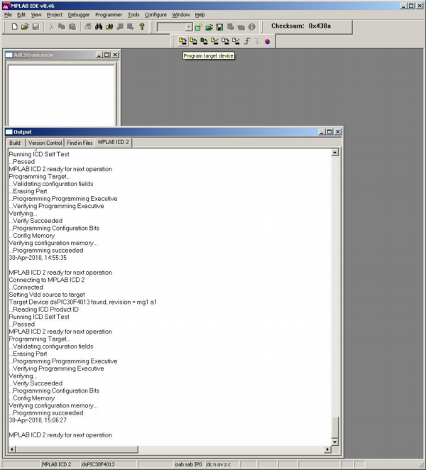
- Click on
Program target deviceand wait the process to end verifying that no errors are rised.
5 Firmware install
On the Ubuntu machine/partition
- attach the USB/CAN model 2066 to pc
- attach the DB9 to USB/CAN
- attach the molex 4 pins connector to the MAIS board
- In a shell type
sudo ip link set can0 type can bitrate 1000000
sudo ip link set up can0
this allows you to communicate with the CAN device.
-
Now launch:
FirmwareUpdater -a -
select
SOCKET_CANand thenDiscover - Download the mais firmware
- select
Upload Applicationand select themais.hexfile just downloaded - select
Cahnge CAN addresschange CAN ADDRESS to5
6 Mount Capacitor Array
Mount the Capacitor array, 4x100nF, 16V, 20%, X7R, SMD, 1206 on the C15 position
7 Test Hall Sensors
Connect the Hall sensors (3) to one of the connectors of the mais to be tested
On the Windows 10 machine/partition
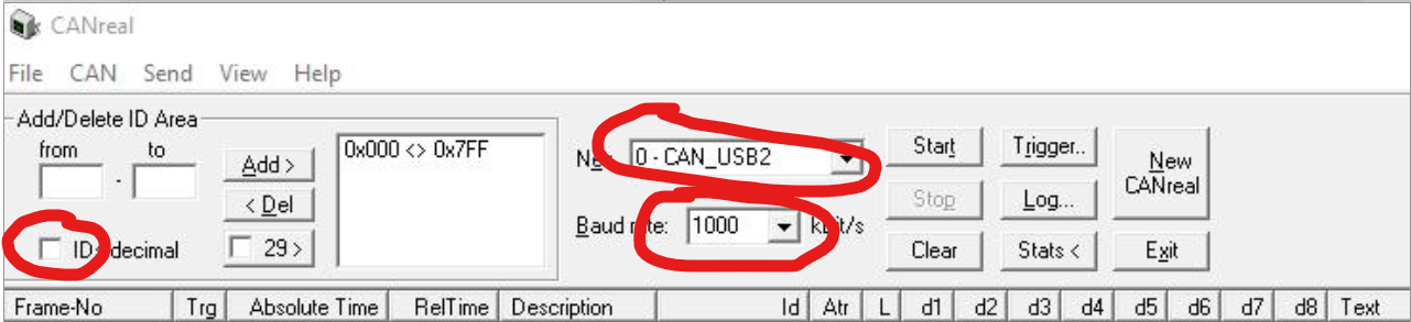
- launch the app
CANreal - Select the following parameters:
- Click on “Start”
- On the bottom, make sure that the parameters correspond to these in the picture:

- Click on “Send”
At this point the software starts to print data and you can leave it in the background.
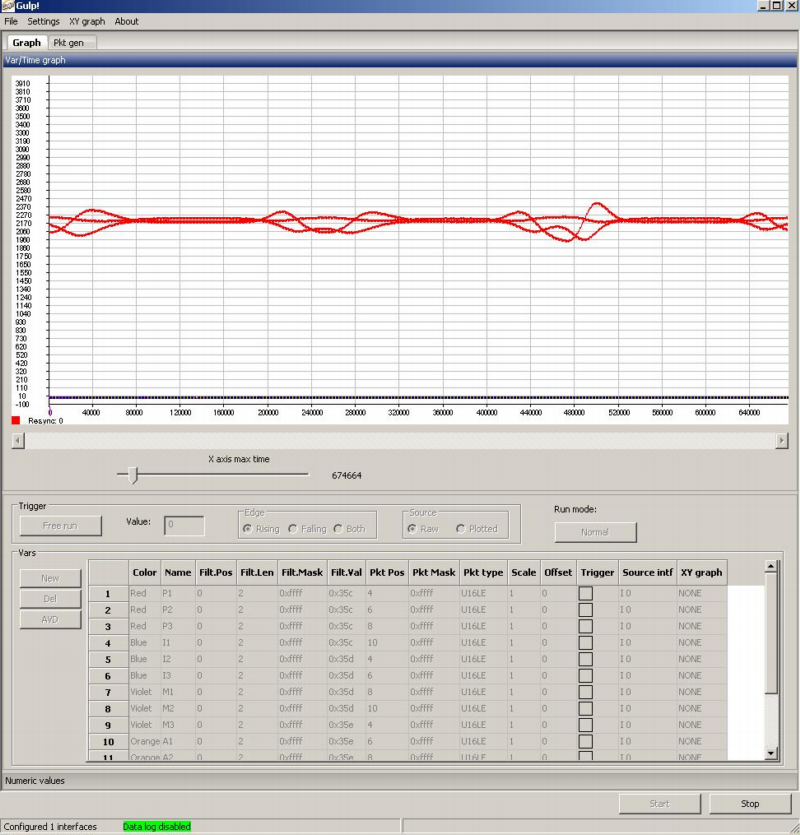
- Run
GULP File->Load Parameters...and selectAdCMais8bit.Xgupin the previously extracted folder- Click
Start - Move the magnet (4) near the hall sensors and check that the three lines plotted in
GULPmove
Repeat the operation in point 7 for the other connectors on the mais
Note
Once done the test for each connector, please revert the CAN ID back to 14.