BOARDS PROGRAMMING
Revision history
| Rev. | Department | Prepared by | Date | Revision description |
|---|---|---|---|---|
| 0 | iCubFacility | D.Tomé | 14/12/2014 | First Emission |
| 1 | icub-tech-iit | D.Tomé | 31/03/2020 | Update for using ST-LINK programmer; added MC4PLUS, MTB4 and STRAIN2 boards |
| 2 | icub-tech-iit | D.Tomé | 20/06/2020 | migrated to markdown |
| 3 | icub-tech-iit | D.Tomé | 31/07/2020 | added programming procedure for BDC BCB RFE_MASTER boards |
| 4 | icub-tech-iit | A.Mura | 10/05/2021 | added programming procedure for BMON boards |
| 5 | icub-tech-iit | A.Mura | 20/06/2022 | added programming procedure for BAT boards |
| 6 | icub-tech-iit | J.Losi | 24/07/2024 | updated programming procedure for BAT boards |
1 Document Scope
Info
This procedure shows how to flash Bootloader and Firmware, change the IDs for CAN based boards and assign the IP address for ETH boards.
2 Boards Programming
2.1 EMS4
2.1.1 HW Requiremnts
- Power Supply 24Vdc @1A
- MICROFIT3toWIRE (IIT Code
5031.A) - EMS-EADP + ETHCROSS (IIT Code
1519.Aand2928.B) - ST-LINK/V2 (IIT Code
13499)
2.1.2 SW Requiremnts
- PC with Windows 10
icub-firmware-buildrepoSTM32 ST-LINK Utilityinstalled on the PCFirmwareUpdatertool compiled on your machine (or you can use a pre-configured VM)
2.1.3 Setup connections
- Connect ST-LINK programmer to the pc and to the P1 connector of EMS4 (4)
- Connect EMS-EADP to the pc and to the P3 connector of EMS4 using ETHCROSS (5)
- Connect the power supply to the P12 connector of EMS4 (4)
2.1.4 Flash bootloader and application
- On the Windows machine go to the
icub-firmware-buildrepo installation folder and browse toicub-firmware-build\ETH\EMS\scripts\st-link - Run
git pull - Set the power supply to 24Vdc@1A and power on
- Double click on
st-link_EMS.bat
2.2 STRAIN2
2.2.1 HW Requiremnts
- ESD USB-CAN with usb power supply cable. (IIT Code
1014) - STRAIN2_ADC Test equipment (IIT Code
12465) - ST-Link debugger (IIT Code
13499) - STRAIN2 programming Interface (IIT Code
12348) only if needed to reprogramm STRAIN2 incased (mounted)
2.2.2 SW Requiremnts
- PC with Windows 10
icub-firmware-buildSTM32 ST-LINK Utilityinstalled on the PC
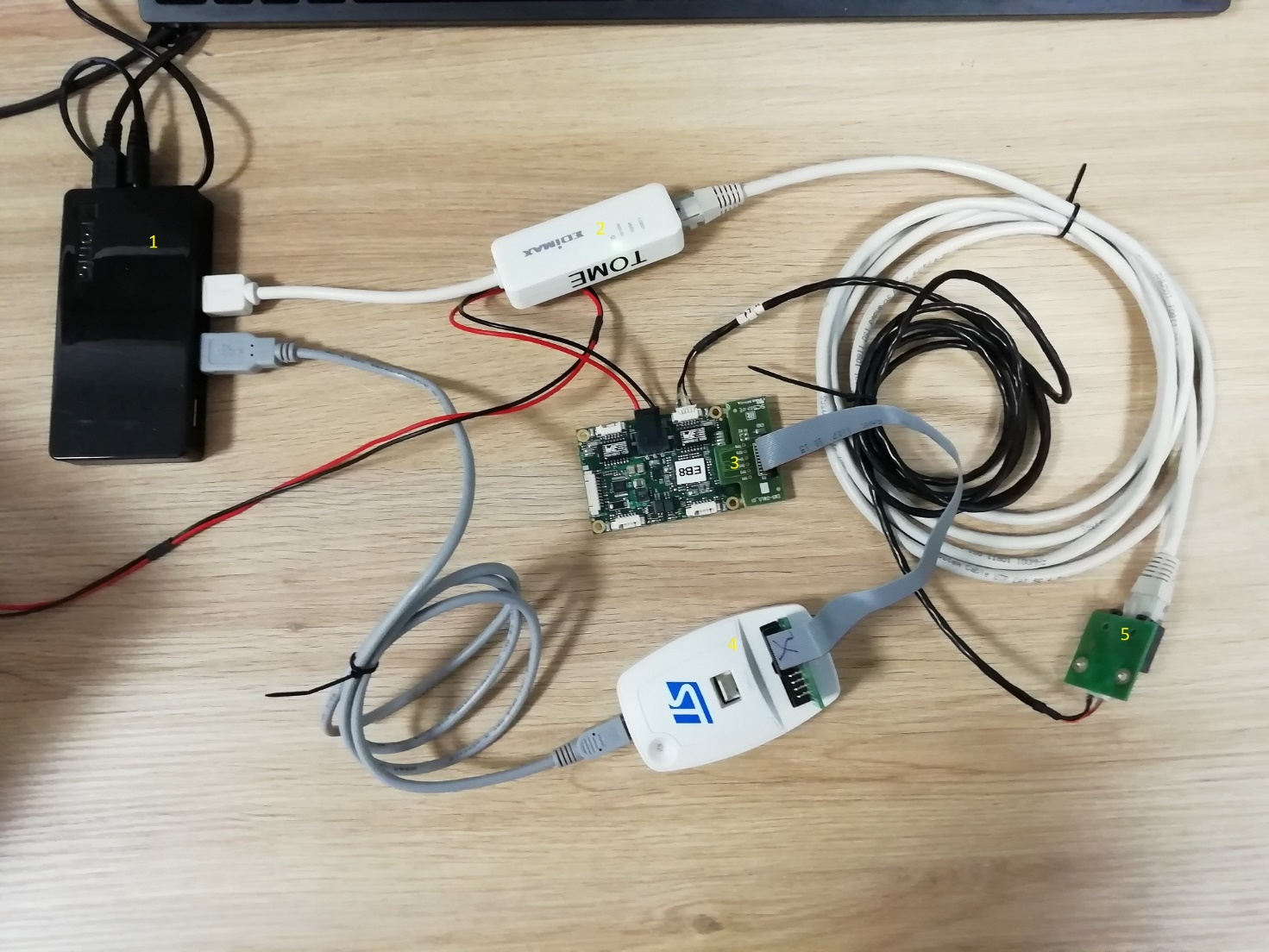
2.2.3 Setup connections
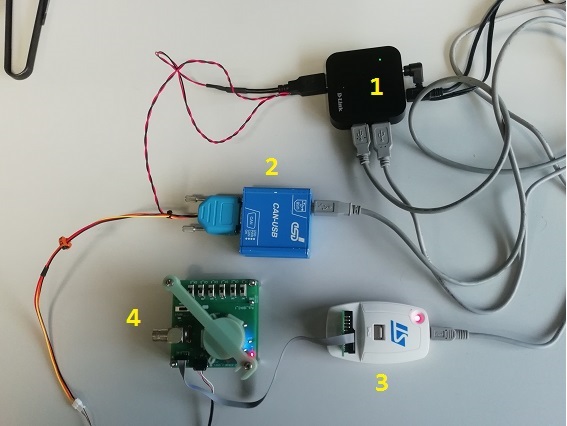
2.2.3.1 Board programming on pcb
- Connect ESD CAN-USB (2) and ST-Link (3) to the PC’s USB (1)
- Connect ESD CAN-USB (2) to the STRAIN2_ADC (4)
- Connect ST-Link (3) to the STRAIN2_ADC (4)
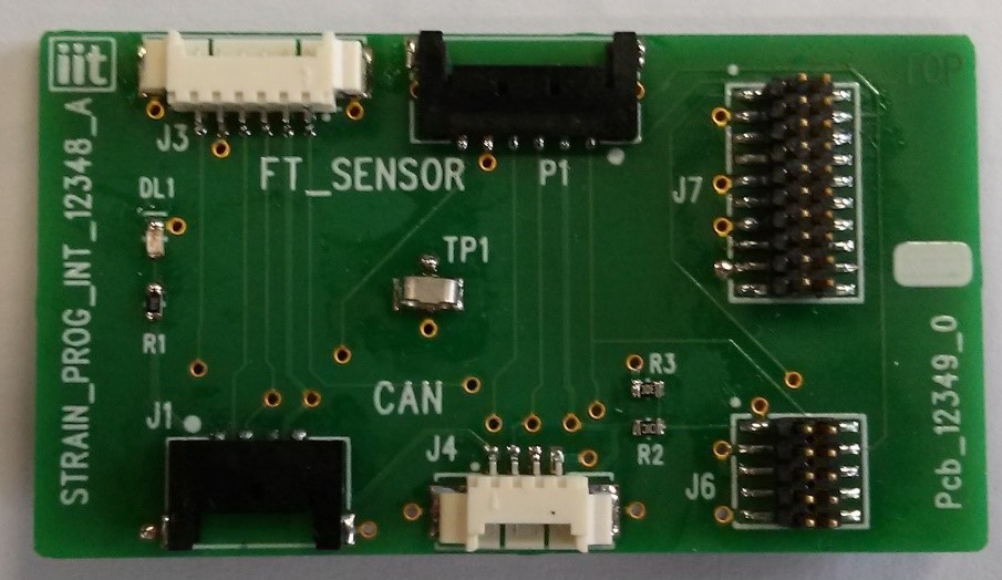
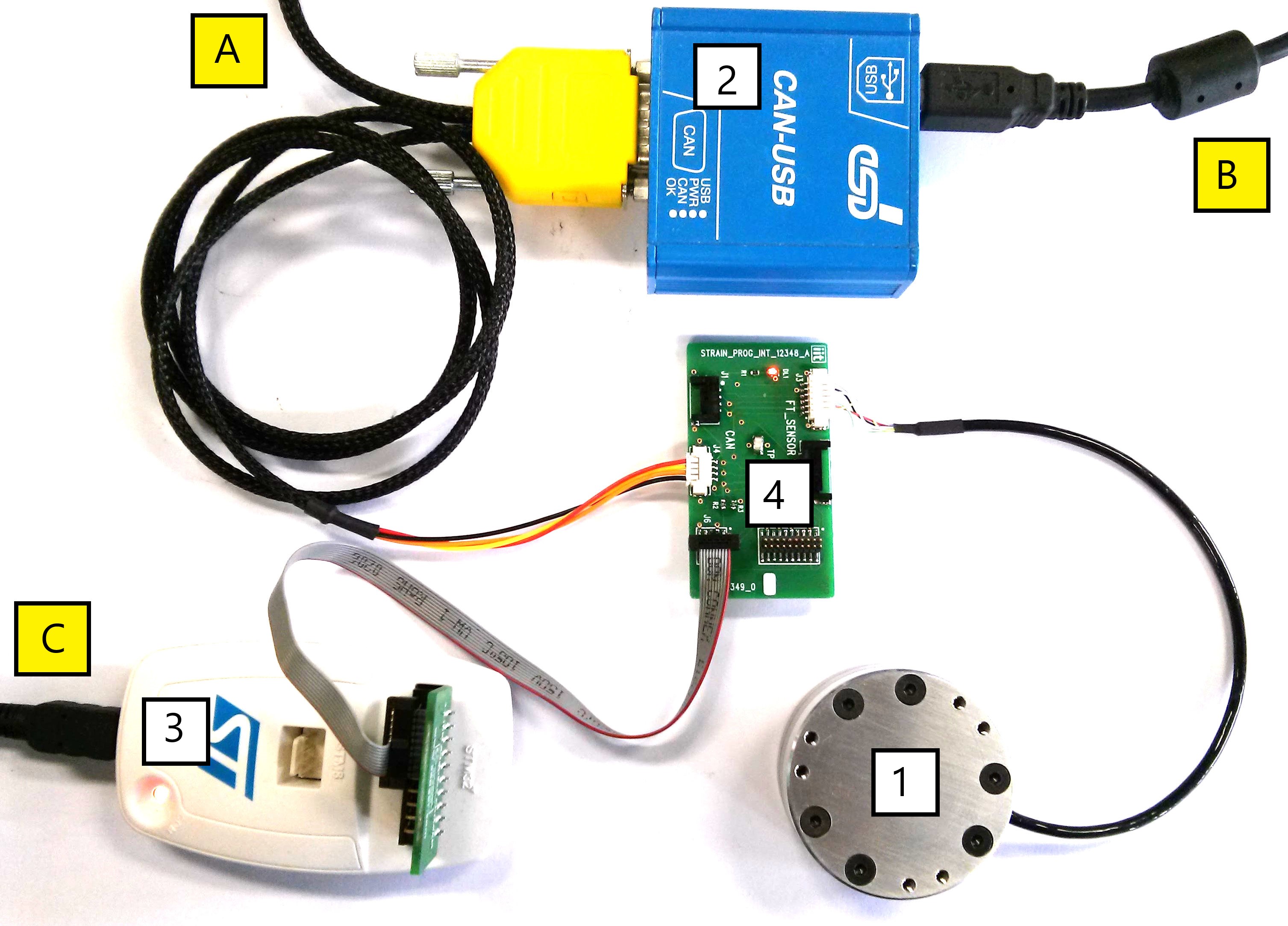
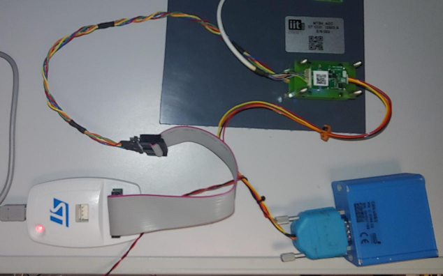
2.2.3.2 Board programming already mounted inside F/T sensor case
- Connect ESD CAN-USB (2-A e 2-B) and ST-Link (3-C) to the PC’s USB ports
- Connect ESD CAN-USB (2) to the STRAIN2_PROG_INT (4)
- Connect ST-Link (3) to the STRAIN2_PROG_INT (4)
- Connect STRAIN2 (1) to STRAIN2_PROG_INT (4)
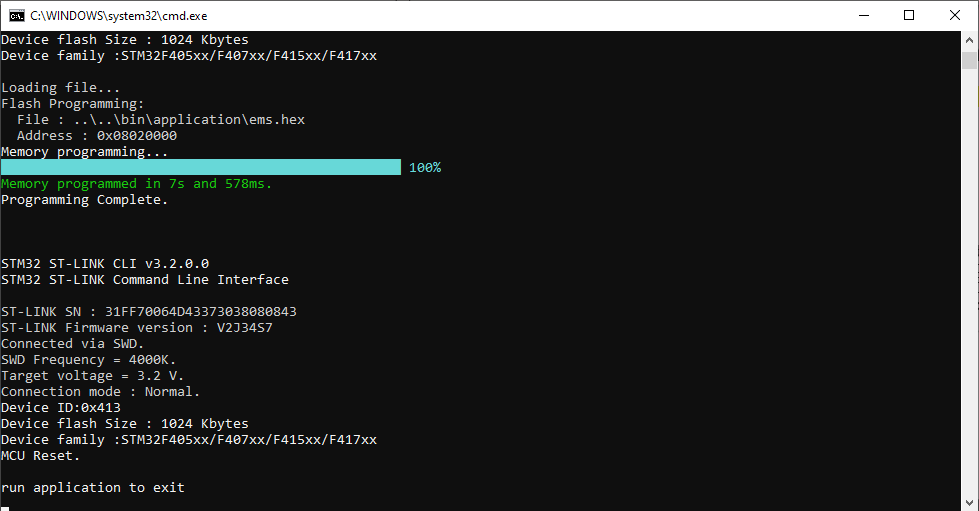
2.2.4 Flash bootloader and application
- On the Windows machine go to the
icub-firmware-buildrepo installation folder and browse toicub-firmware-build\CAN\strain2\st-link - Run
git pull - Double click on
st-link_STRAIN2.bat
2.3 MTB4
2.3.1 HW Requiremnts
- ESD USB-CAN with usb power supply cable. (IIT Code
1014) - MTB4_ADC Test equipment (IIT Code
12603) - ST-Link debugger (IIT Code
13499)
2.3.2 SW Requiremnts
- PC with Windows 10
icub-firmware-buildrepoSTM32 ST-LINK Utilityinstalled on the PC
2.3.3 Setup connections
- Connect ESD CAN-USB (2) and ST-Link (3) to the PC’s USB (1)
- Connect ESD CAN-USB (2) to the MTB4 (MTB4-J1)
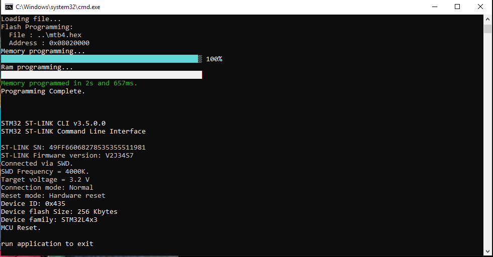
2.3.4 Flash bootloader and application
- On the Windows machine go to the
icub-firmware-buildrepo installation folder and browse toicub-firmware-build\CAN\mtb4\st-link - Run
git pull - Double click on
st-link_MTB4.bat
2.4 MC4
2.4.1 HW Requiremnts
- Power Supply 12Vdc @1A
- An MCP board (IIT Code
3176) - ESD USB-CAN (IIT Code
1014) - Code Warrior Programmer USB TAP (IIT Code
361)
2.4.2 SW Requiremnts
- PC with Windows 10
icub-firmwarerepoicub-firmware-buildrepoCodeWarrior® Development Studio for 56800/E 8.3installed on the PC
2.4.3 Setup connections
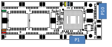
- Connect, with an 8 wires flat cable, one of the four output headers from the MCP board with the P10 header from the MC4 board.
- Connect the programmer Code Warrior USB TAP with the header P1 on the MC4 board (see Figure 3).
- Give power to MC4 via MCP by the mean of a 12V power supply.
- Check that the following LEDs turn on (see Figure 3): a. DL3 = orange b. DL4 = red c. DL5 = green.
2.4.4 Flash bootloader and application
Bootloader
- Browse to the folder
loader56f807from your localicub-firmwarerepository. - Run
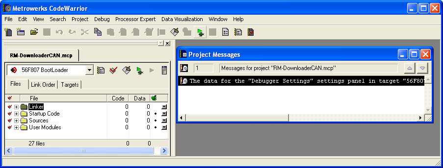
git pull - Launch CodeWarrior IDE
- Open the project
RM-DownloaderCAN.mcp - Press the
playicon (debug mode) that loads the BootLoader routines into theMC4flash memory and run the debug session.
- When done with the downloading of bootloader routines, you should see the led DL1 (YELLOW) and DL2 (BLUE) turned on for few seconds to indicate that everything went well, afterwards no need to run the debug mode, just stop it by pressing the red cross “STOP” and quit CodeWarriorIDE.
Firmware
- Connect the USB/CAN to the board
- Power ON the board
- In the first 5 seconds click Connect from
FirmwareUpdater - Go to your
icub-firmware-buildand do agit pull - Select
Upload Applicationand choose the desired firmware version inicub-firmware-build/CAN/4dc
2.5 BLL
2.5.1 HW Requiremnts
- Power Supply 24Vdc @1A
- A BLP board (IIT Code
1482.A) - ESD USB-CAN (IIT Code
1014) - Code Warrior Programmer USB TAP (IIT Code
361)
2.5.2 SW Requiremnts
- PC with Windows 10
icub-firmwarerepoicub-firmware-buildrepoCodeWarrior® Development Studio for 56800/E 8.3installed on the PC
2.5.3 Setup connections
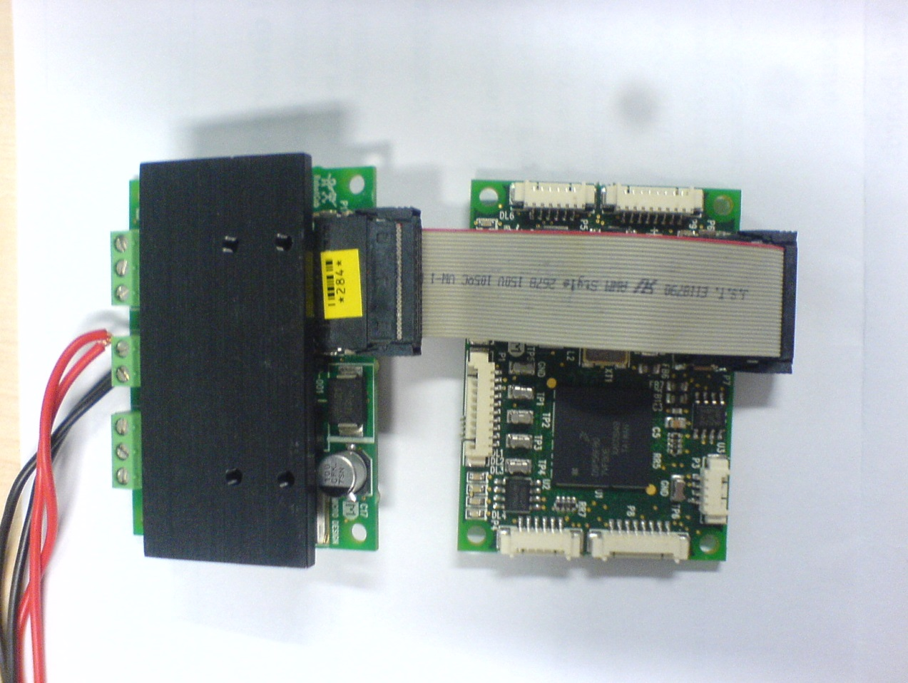
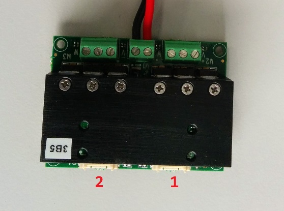
- Connect, with flat ribbon cable, the BLP board with the BLL board
Warning
Pay attention to the red cable from the flat ribbon cable (on the top side)
- Give power to
BLLviaBLPby the mean of a24Vdc @1Apower supply. - Connect the programmer
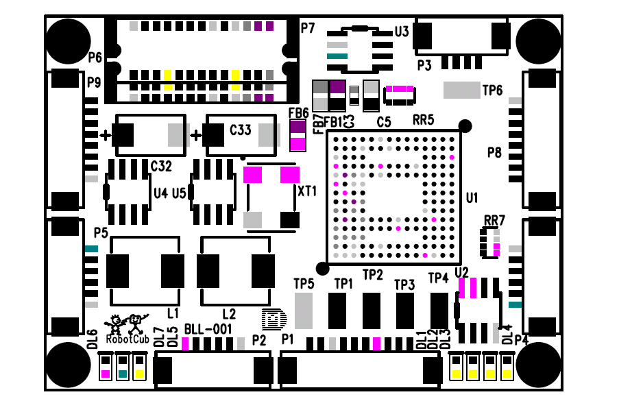
Code Warrior USB TAPwith the headerP1from theBLLboard, and see the leds turn on (DL4,DL5,DL6andDL7) while ledDL1blinking.
2.5.4 Flash bootloader and application
Bootloader
- Browse to the folder
loader56f807from your localicub-firmwarerepository. - Run
git pull - Launch CodeWarrior IDE
- Open the project
RM-DownloaderCAN.mcp - Press the
playicon (debug mode) that loads the BootLoader routines into theBLLflash memory and run the debug session.
Firmware
- Connect the USB/CAN to the board
- Power ON the board
- In the first 5 seconds click Connect from
FirmwareUpdater - Go to your
icub-firmware-buildand do agit pull - Select
Upload Applicationand choose the desired firmware version inicub-firmware-build/CAN/2bll
2.6 2FOC
2.6.1 HW Requiremnts
- Power Supply 30Vdc @1A
- ESD USB-CAN (IIT Code
1014) - Microchip ICD3 (IIT Code
4034) - 2FOC Test Setup (IIT code
4569.A)
2.6.2 SW Requiremnts
2.6.3 Setup connections
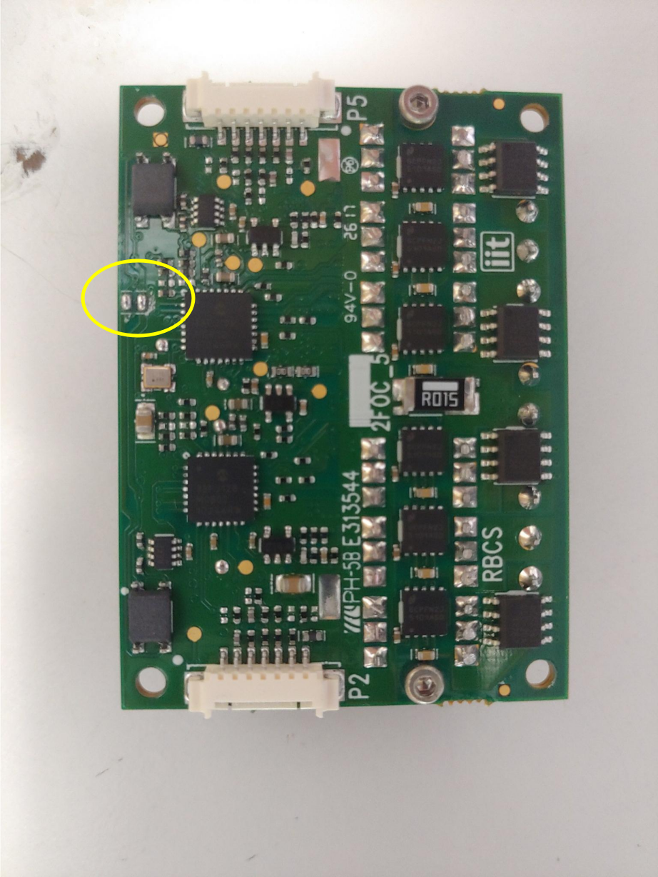
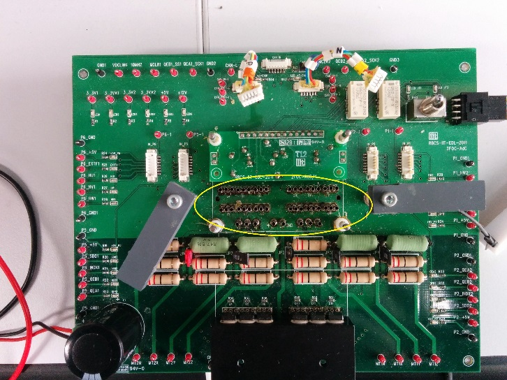
Info
Make sure that the following highlighted jumpers are closed
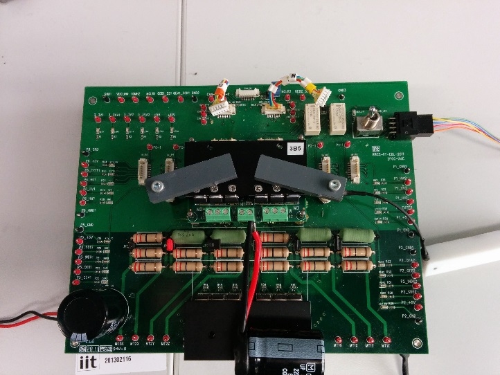
- Connect the
2FOCtest fixture to the 30Vdc @1A power supply - Place the
2FOCon the setup
Info
if board mounts heatsink remove all nails highlighted below
- Connect the
ICD3to the setup - Connect the USB/CAN to the board
- Power on the
2FOC
2.6.4 Flash bootloader and application
Bootloader
- Open bootloader MPLAB project at
icub-firmware\emBODY\eBcode\arch-dspic\board\any\env\bootloader\proj-bootloader\bootloader.mcw File->Importthen browse to :firmware\emBODY\eBcode\arch-dspic\board\any\env\bootloader\bin\bootloader-2foc.hex- Place the switch
SW1on the setup pointing left side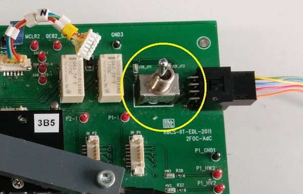
- Click on
Erase - Click on
Program - Open
FirmwareUpdaterand clickDiscover - Change id : 1 (or 3) if SW1 is pointing left (P3 on 2FOC) or 2 (or 4) if
SW1is pointing right (P4 on 2FOC)
Warning
For convention, Id for 2FOC’s P3 must always smaller than the one for P4
- Move
SW1pointing right and repeat all steps from 4 to 7
Firmware
- Connect the USB/CAN to the board
- Power ON the board
- In the first 5 seconds click Connect from
FirmwareUpdater - Go to your
icub-firmware-buildand do agit pull - Select
Upload Applicationand chooseicub-firmware-build/CAN/2foc/2foc.hex
2.7 MC4PLUS
2.7.1 HW Requiremnts
- Power Supply 24Vdc @1A
- ST-LINK/V2 (IIT Code
13499)
2.7.2 SW Requiremnts
- PC with Windows 10
icub-firmware-buildrepoSTM32 ST-LINK Utilityinstalled on the PCFirmwareUpdatertool compiled on your machine (or you can use a pre-configured VM)
2.7.3 Setup connections
- Connect
ST-LINKprogrammer to the pc and to theP1connector ofMC4PLUS - Connect the power supply to the
P7connector ofMC4PLUS
2.7.4 Flash bootloader and application
- On the Windows machine go to the
icub-firmware-buildrepo installation folder and browse toicub-firmware-build\ETH\MC4PLUS\scripts\st-link - Run
git pull - Set the power supply to 24Vdc@1A and power on
- Double click on
st-link_MC4PLUS.bat
2.8 BDC
2.8.1 HW Requiremnts
- Power Supply 12Vdc @0.5A
- ST-LINK/V2 (IIT Code
13499)
Warning
Take care to cut off the pin 7 of J1 (Figure 1) and to close the jumper JP1 near R63 (Figure 2)
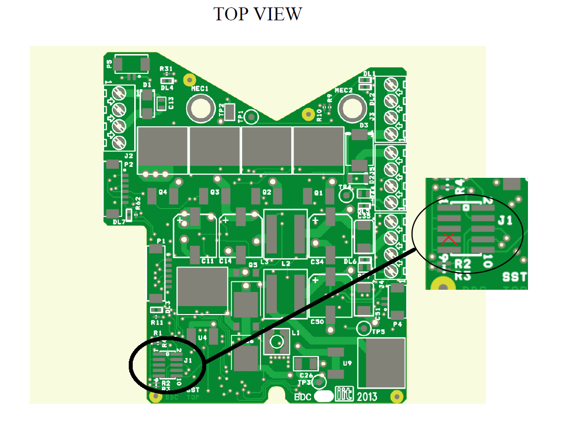
Figure 1
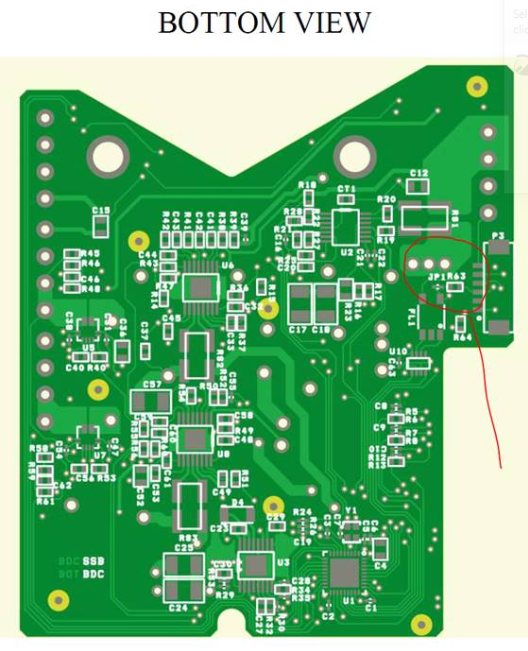
Figure 2
2.8.2 SW Requiremnts
- PC with Windows 10
icub-firmware-buildrepo intodevelbranchSTM32 ST-LINK Utilityinstalled on the PC
2.8.3 Setup connections
- Connect
ST-LINKprogrammer to the pc and to theP1connector ofBDC - Connect the power supply to the
J2connector ofBDC
2.8.4 Flash bootloader and application
- On the Windows machine go to the
icub-firmware-buildrepo installation folder and browse toicub-firmware-build\CAN\bdc\st-link - Run
git pull - Set the power supply to
12Vdc @0.5Aand power on - Double click on
st-link_BDC.bat
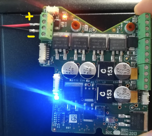
2.9 RFE_MASTER
2.9.1 HW Requiremnts
- ST-LINK/V2 (IIT Code
13499)
Warning
Take care to cut off the pin 7 of J8 and close the jumper J7 (Figure 1 -> 1,2)
2.9.2 SW Requiremnts
- PC with Windows 10
icub-firmware-buildrepo intodevelbranchSTM32 ST-LINK Utilityinstalled on the PC
2.9.3 Setup connections
- Connect
ST-LINKprogrammer to the pc and to theJ8connector ofRFE_MASTER(Figure 1 -> 1) - Connect a
MICRO-USBcable toJ9connector ofRFE_MASTERto power on the board (Figure 1 -> 3)
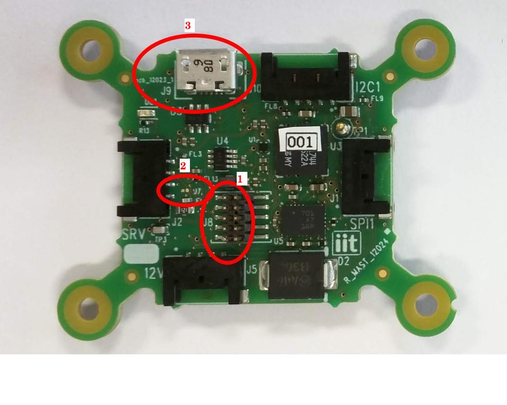 Figure 1
2.9.4 Flash bootloader and application
- On the Windows machine go to the
icub-firmware-buildrepo installation folder and browse toicub-firmware-build\CAN\rfe\st-link - Run
git pull - Double click on
st-link_RFE.bat
2.10 BCB
2.10.1 HW Requiremnts
- Power Supply 12Vdc @0.5A
- ST-LINK/V2 (IIT Code
13499)
Warning
Take care to cut off the pin 7 of J1 (Figure 1)
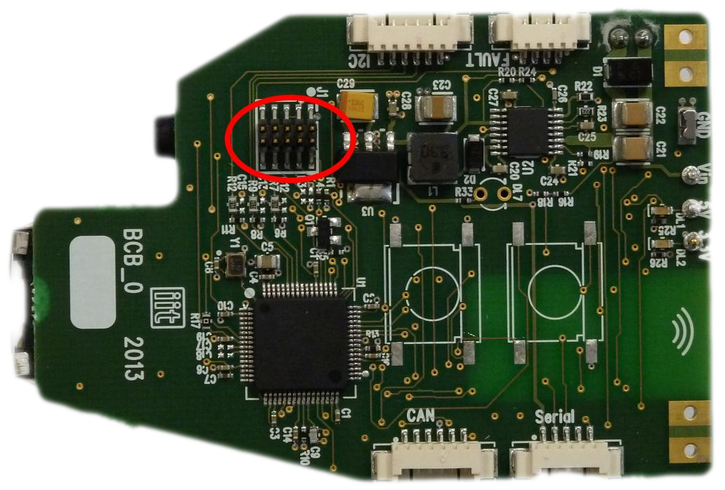
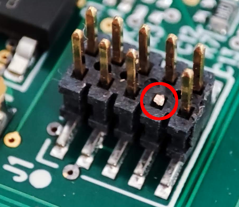
Figure 1
2.10.2 SW Requiremnts
- PC with Windows 10
icub-firmware-buildrepo intodevelbranchSTM32 ST-LINK Utilityinstalled on the PC
2.10.3 Setup connections
- Connect
ST-LINKprogrammer to the pc and to theP1connector ofBCB - Connect the power supply to the
J3connector ofBCB
2.10.4 Flash bootloader and application
- On the Windows machine go to the
icub-firmware-buildrepo installation folder and browse toicub-firmware-build\CAN\bcb\st-link - Run
git pull - Set the power supply to
12Vdc @0.5Aand power on - Double click on
st-link_BCB.bat
2.11 BMON
2.11.1 HW Requiremnts
- Microchip ICD3 programmer
- No power supply is needed
- adapter cable
 NOTE: The adapter cable is made with the self-test cable provided with the Microchip ICD3 kit, and the two connectors at the end are not simmetric: cut one and keep the following (color sequence:
 BLUE - YELLOW - GREEN - RED - BLACK - WHITEfrom left to right)
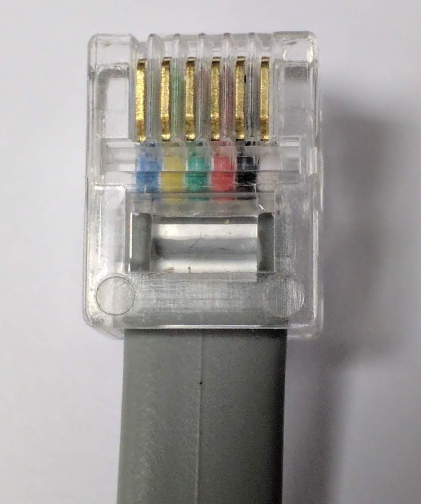
At the cut end solder a 2.54mm pitch pin strip, 5 pins (BLACK - WHITE - YELLOW - GREEN - RED, the blue is not connected):
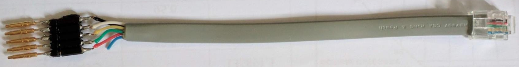
NOTE: in this configuration, RED wire is the GROUND, and BLACK wire is the 3.3V!
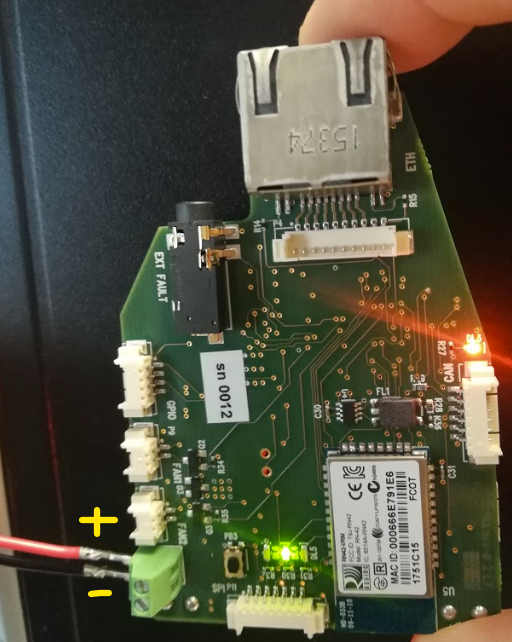
NOTE: remember to solder the transzorb D2 (iitcode 5929) on the dedicated battery pads:
![]()
2.11.2 SW Requirements
2.11.3 Setup connections
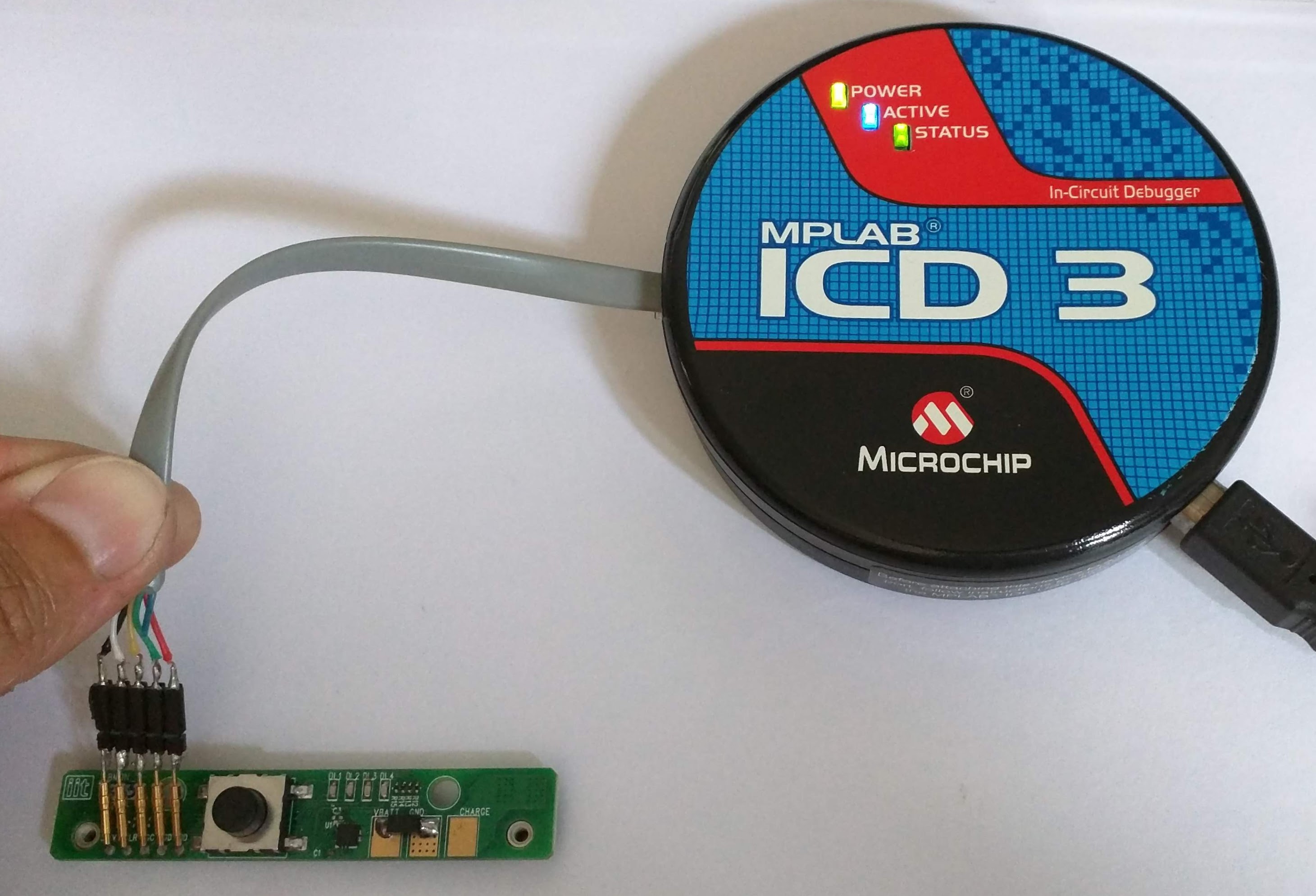
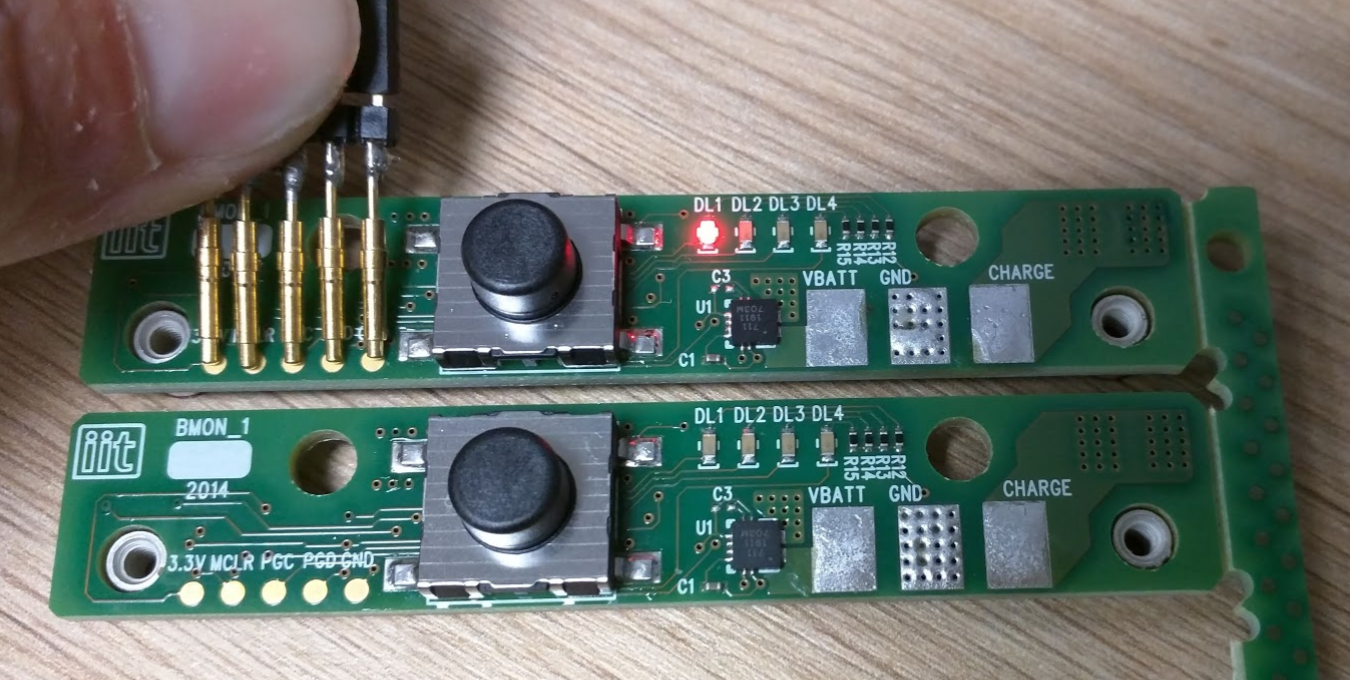
- Connect the adapter cable to the Microchip
ICD3programmer, and press the pin strip on theBMONboard as shown in the following picture:
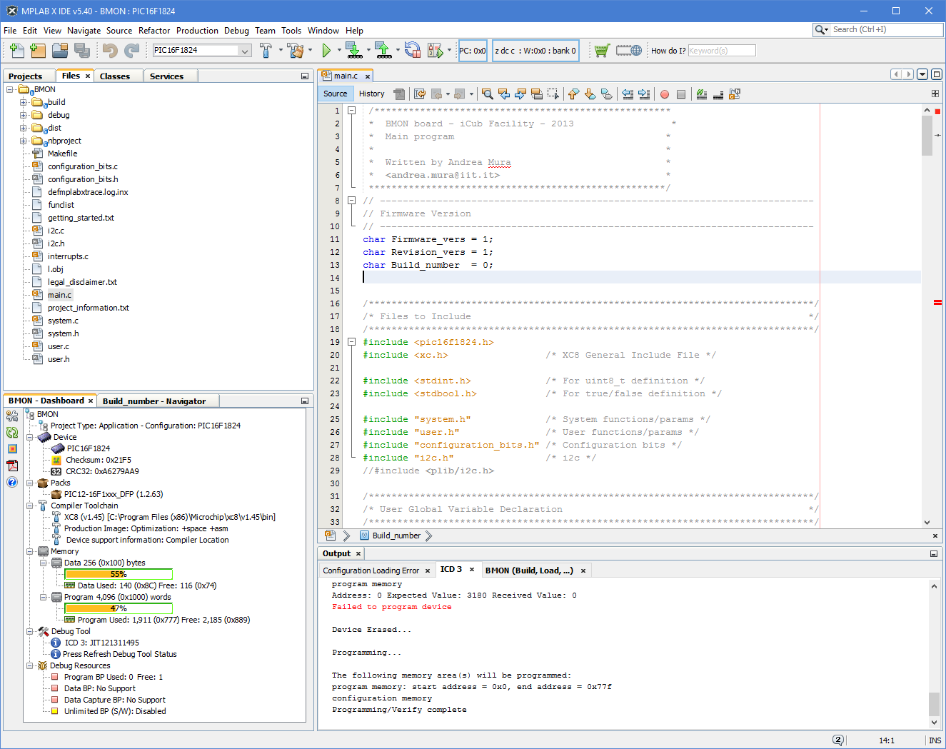
2.11.4 Flash bootloader and application
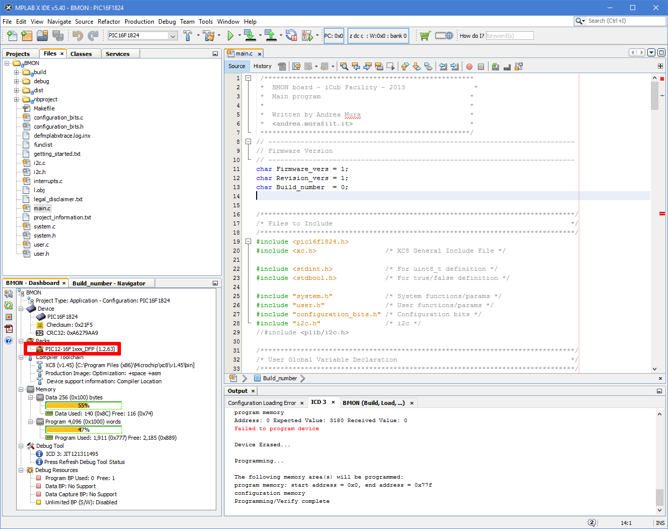
- Launch MPLAB IDE and open the BMON project:
- Click on the left menu on PIC12-16F
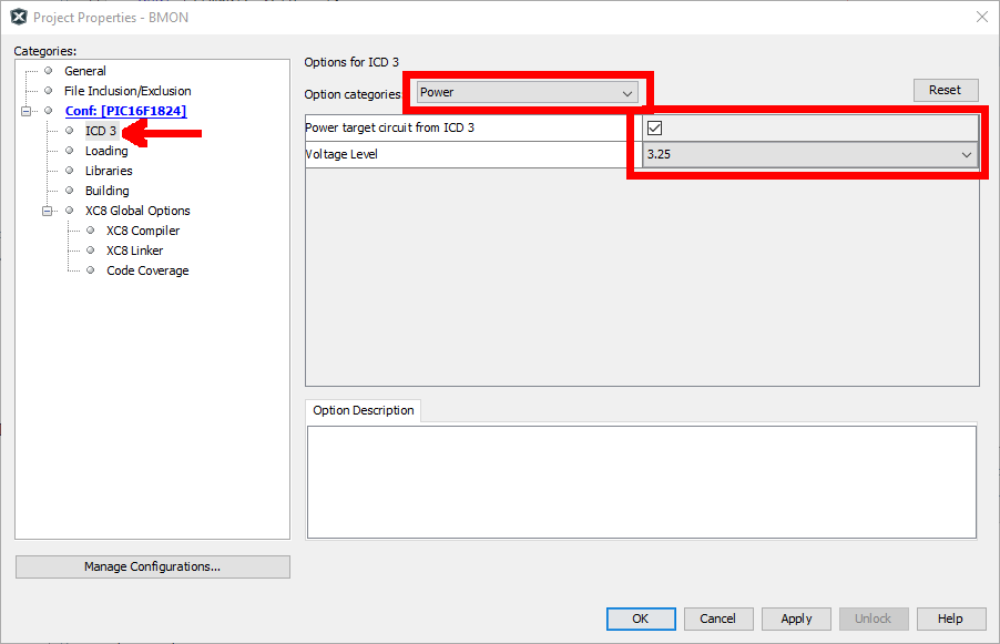
- A new window appears; select
ICD3,Powerin the Option categories menu, check the box Power target circuit from ICD3, and select3.25in the Voltage Level menu:
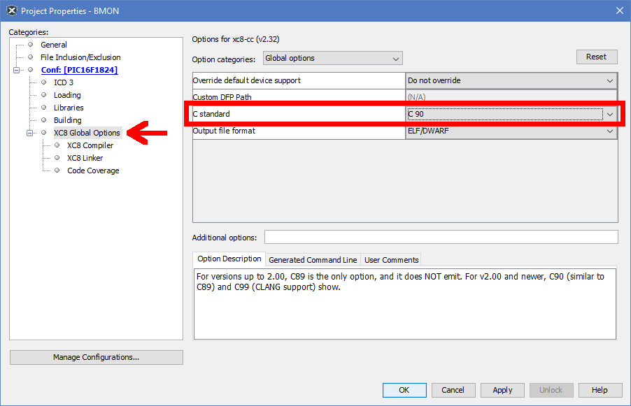
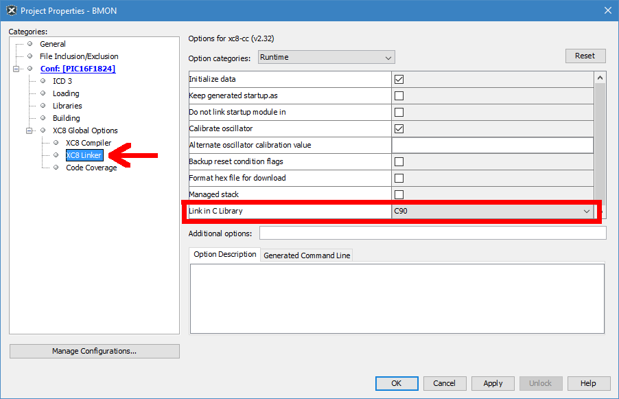
- To avoid issues due to newer XC8 versions, put these the following two settings in the Project Properties:
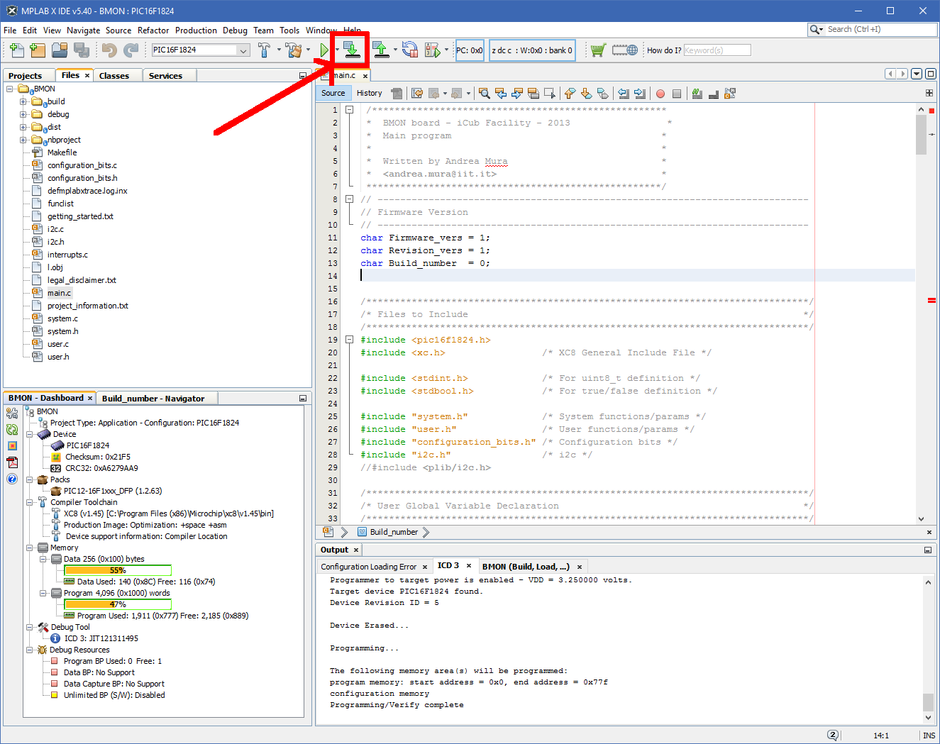
- Click on the following icon to program the board:
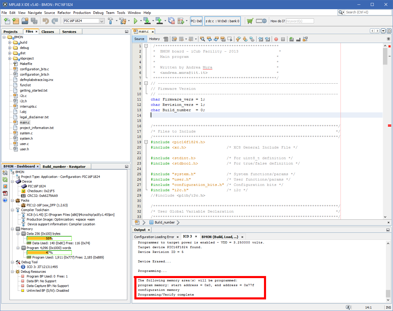
- At the end a Programming/Verify complete message confirms the good programming, and the
LD1red LED on theBMONstart to blink:
2.12 BAT
2.12.1 HW Requiremnts
- Power Supply 12Vdc @0.5A
- ST-LINK/V3 (IIT Code
16461)
Warning
Take care to cut off the pin 7 of J1 (Figure 1)

Figure 1
2.12.2 SW Requirements
- PC with Windows 10
Gitbash or GUI software such as GitTortoise, GitKraken or GitDesktop installed (necessary for cloning and fetchingicub-firmware-buildrepository)icub-firmware-buildrepo intomasterbranchSTM32CubeProgrammerinstalled on the PC at the pathC:\Program Files\STMicroelectronics\STM32Cube\STM32CubeProgrammer\bin(which should be the default one)
2.12.3 Setup connections
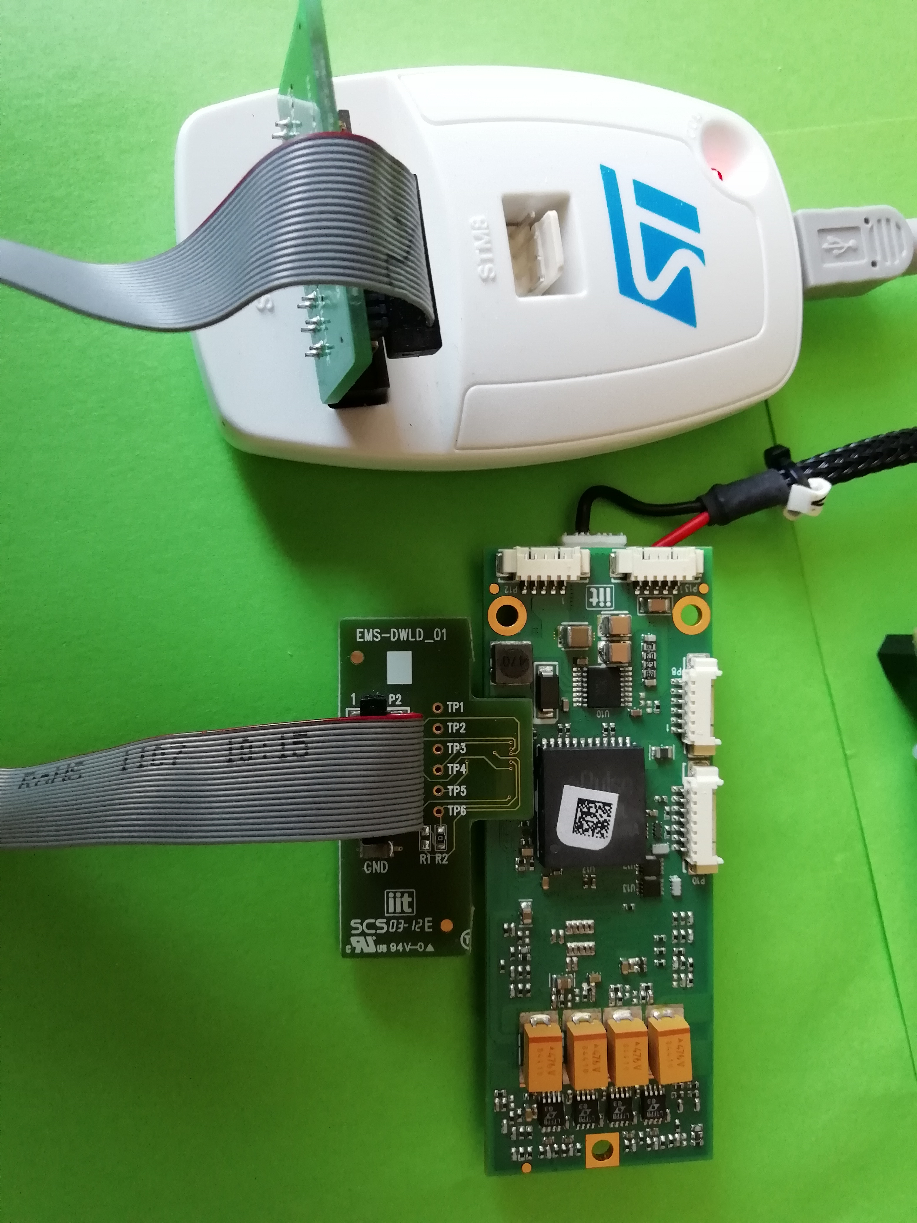
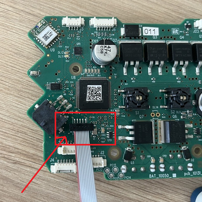
- Connect
ST-LINK/V3programmer to the pc and to theJ1connector ofBATusing the thinner flat cable among the ones provided with theST-LINK/V3, which is the one with 10/14 (BAT/programmer sides) pins.
Note
If the flat cable you are using does not have the hole corresponding to the pin7 of J1 connector blocked up, for a proper connection keep in mind that the flat cable should be connected so that the red line on the cable is over the pin signed with a small white dot on the serigraphy. Figure below shows how the cable should be connected.
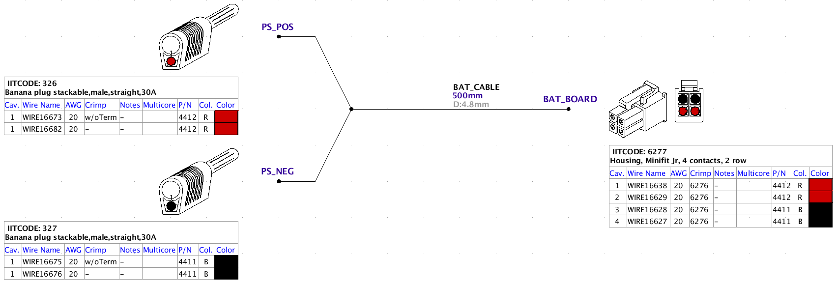
- Connect the power supply to the
J18orJ19connectors ofBAT(a proper cable is mandatory)
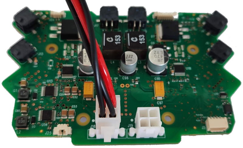
The cable is the following:
2.12.4 Flash bootloader and application
- Supposed you have the
icub-firmware-buildrepository installed in your pc, you can proceed with the subsequent steps. Otherwise does the following to install it and align with themaster (stable)branch- Go to this link and clone the repo by typing on a terminal in a desired directory on your laptop the command:
git clone https://github.com/robotology/icub-firmware-build.git - The go to the folder
icub-firmware-buildand run the commandgit fetch origin(or the name you gave to the remote, by default isorigin) and thengit pull origin masterso that you have downloaded locally all the remote updates. - Note that the previous steps can also be done using a git-related GUI software such as, gitTortoise, Github Desktop or similar.
- Go to this link and clone the repo by typing on a terminal in a desired directory on your laptop the command:
- On the Windows machine go to the
icub-firmware-buildrepo installation folder and browse toicub-firmware-build\CAN\bat\st-link - Run
git pull origin masterso you are aligned to all the remote updates (you will do so only if you already have the repository installed and you skipped the sub-stepsa-c. Otherwise you will be already aligned with the latest updates). - Set the power supply to
12Vdc @0.5Aand power on - Double click on
st-link_BAT.bat - Type 1 or 2 to select the firmware target (ergoCub-iCub or R1)
3 Boards Common actions
3.1 Change IP Address to ETH boards
Info
This applies to all ETH boards
Warning
If you are using a Linux based OS remember to run in a terminal the following commands to be able to use the ESD USB/CAN device:
sudo ip link set can0 type can bitrate 1000000
sudo ip link set up can0
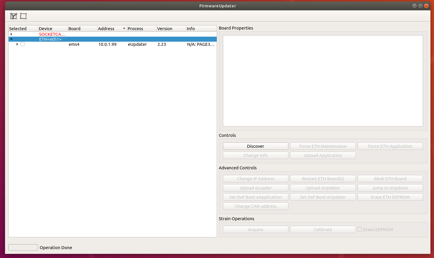
- Run
FirmwareUpdater -aand selectETH<eth1>in the device list and then click on theDiscoverbutton. You should see the board:
-
Now select the board (tick the checkbox) and click on
Force ETH Maintenance -
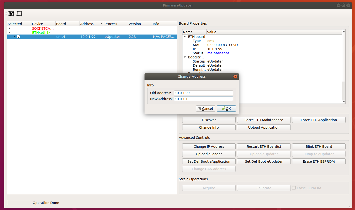
Now select the board (tick the checkbox) and click on
Change IP Address; then set the right IP
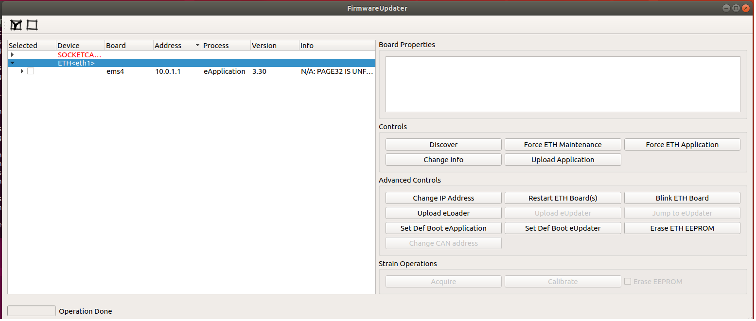
- Click on
Set Def Boot eApplicationand then onRestart ETH Board(s); wait few seconds then click on Discover (withETH<eth1>device selected). You should see the board with the new IP address
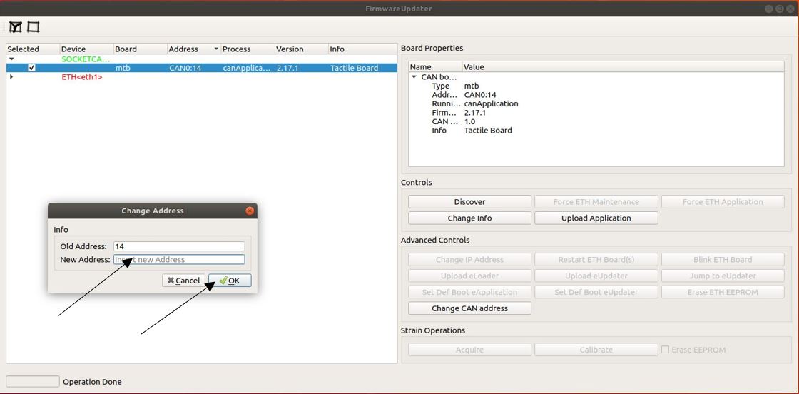
3.2 Change ID to CAN boards
Info
This applies to all CAN boards
Warning
If you are using a Linux based OS remember to run in a terminal the following commands to be able to use the ESD USB/CAN device:
sudo ip link set can0 type can bitrate 1000000
sudo ip link set up can0
- Power on the board
- Run
FirmwareUpdater -aand selectSOCKETCAN<0>for Linux systems orESDCAN<0>for Windows; in the device list and then click on theDiscoverbutton. You should see the board: - Now select the board (tick the checkbox) and click on
Change Can Address; then set the right ID