BAT
Revision history
| Rev. | Department | Prepared by | Date | Revision description |
|---|---|---|---|---|
| 0 | icub-tech-iit | A. Mura | 31/08/2023 | First Emission |
Functional Test
The BAT board is used on iCub3, ergoCub, R1 robots. See programming procedure at this link.
The full test is a bit complicated so it has to be reduced to see the functionality with the LEDs that change once the board is programmed; with this premise, in these conditions, a cable is enough to power it (and possibly a programmer to program it).
The cable can be made like this:
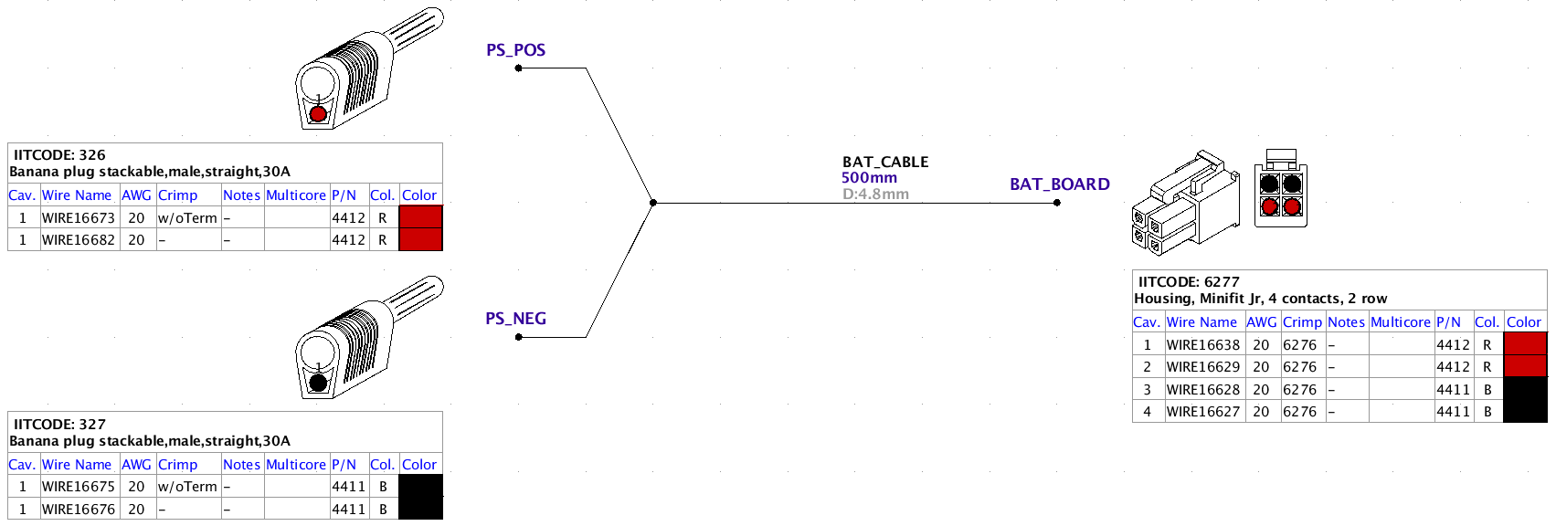
The connector to be connected to the board is a Molex Minifit JR code 39-01-2040, whose crimps are Molex 39-00-0039; on the other side 2 banana plugs or equivalent to be connected to a power supply.
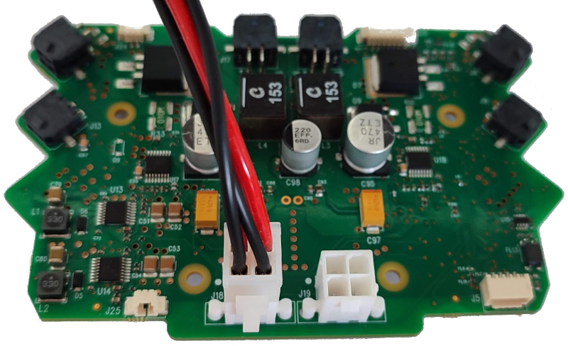
The cable is then connected to one of the two connectors on the board:
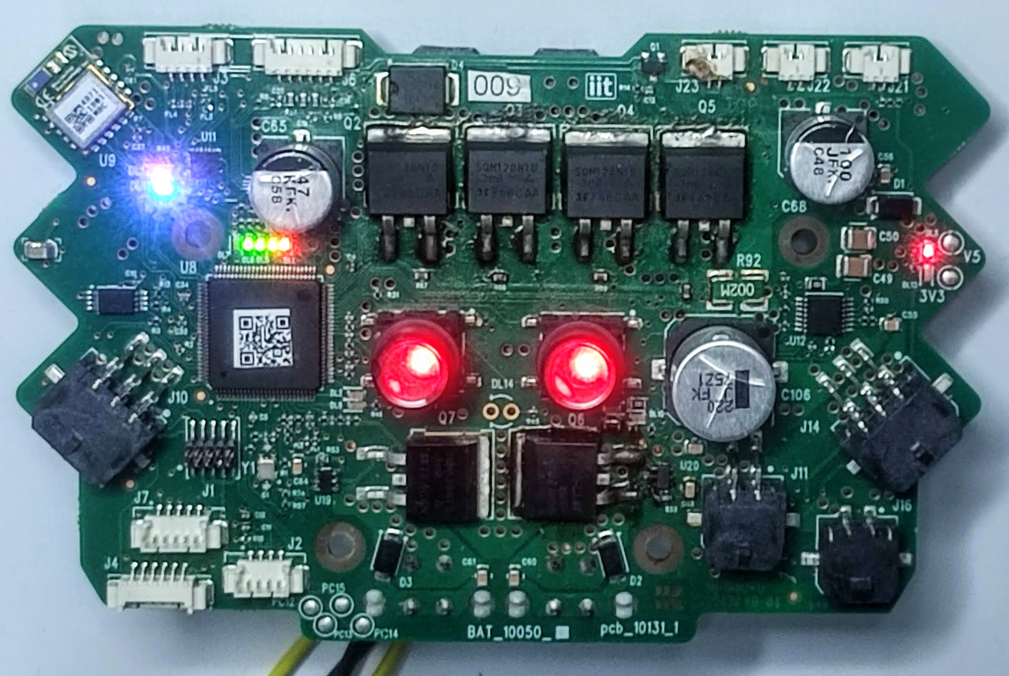
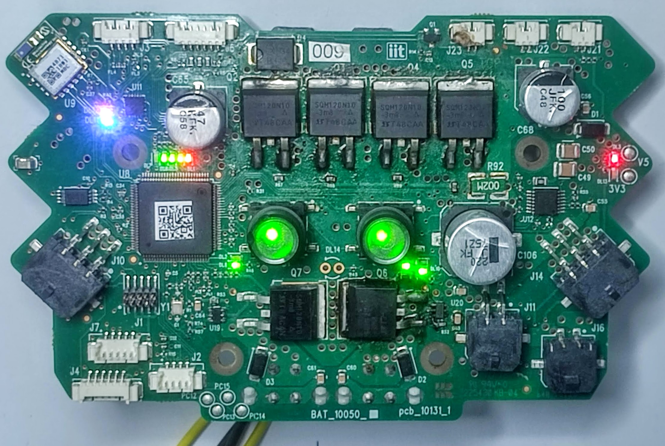
Once the board has been switched on and programmed, you can press the buttons with the LEDs and see if they change color (from red to green for example), and in any case check that the current absorbed is in the order of tens of mA. The power supply voltage ranges from 12V to 48V, and by varying it, more or less of the 5 LEDs arranged in a LED bar will light up.
The BAT should look like this:
To test the ORing section, 2 cables and 2 power supplies are needed, and they must be connected to the J18 and J19 white pcb connectors: this circuit passes the higher voltage. Use a multimeter/oscilloscope to see the net VIN (refer to the schematic).
It could be useful to connect a display to the BAT in order to see electrical parameters and the status of the board: refer to the 4D OLED display guide at this link.
These links indicate how to program the board and the meaning of the button LED colors.
https://icub-tech-iit.github.io/procedures/tp-boards-programming/#212-bat
https://icub-tech-iit.github.io/documentation/robot_power/robot_power_button/