BAT board
Introduction
This page describes the BAT board, its protocol and its ouput data. Basically, this board is responsible for the management of the data and signals provided by the battery pack in R1, iCub, and ergoCub robots. Moreover, it should be noted that in these robots it is always coupled with the BMS board, which is responsible for fine-tuning and managing the battery pack status and described in the specific BMS page.
Firmware
When one aims to update the BAT firmware, the correct .hex version ought be selected from the BAT folder. Specifically, there are two different BAT executables:
- bat.r1.hex: it addresses R1 robot.
- bat.hex: it addresses iCub and ergoCub robots.
There exist two different versions of the BAT FW because the dcdc_management phase is done differently between R1 and iCub/ergoCub.
Specifically, in iCub and ergoCub robots, CPU and motors are handled separately, and they can work detached. By contrast, in R1, they work always together.
Moreover, these robots do have different battery packs, hence the voltage thresholds are customized in the two FW versions.
In general, as shown in the figures below (illustrating the connection between the BAT and EMS boards in ergoCub/SN001 on the left and in the base of R1/SN003 on the right), the BAT can be connected to an EMS board through the CAN connector devoted to receiving the CAN frames sent out by the BAT.
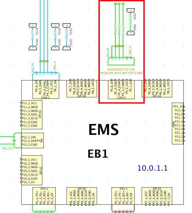 |
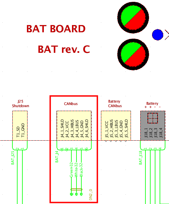 |
Output data
The data transmitted by the BAT board is related to the overall system, whether the robot is on battery or plugged to the external voltage supply.
By contrast, the data transmitted by BMS board is specifically related to the battery pack.
Specifically, at the current status of the development (April 2024), the BAT board can send the following data (which is then elaborated by fw and sw and sent to a yarp port):
- Input Voltage (\(V\)). This can be either the
Battery packvoltage or thePower supplyvoltage depending on how the robot is charged. Anyway, it is always the largest value between the two. - Total Current absorbed by the system (\(A\)) (for the whole robot). This is the total current consumption of the system (the sum of the three currents: 42V HSM (power-supply/battery-pack) + 12V motor + 12V CPU).
- Battery Pack Charge (\(\%\)). It has a value different from
NaNif the robot has theBattery packswitched enabled. - Empty field (NaN). Differently from the
BMSboard, the average temperature is not available on theBATboard. - Battery Pack Status. Currently, it is a bitmask corresponding to
(DCDC_status_B << 8 ) | DCDC_status_A. Please see the Types of data transmitted for theDCDC_status_BandDCDC_status_Ameanings.
Communication characteristics
The BAT board sends the pieces of information detailed above with a FIFO cycle of 100 ms. Then, the EMS board handles the CAN frames sent by the BAT, parses them, and finally forwards them to the higher level of the yarprobotinterface at the specific port defined in the configuration files with a frequency of 1 Hz.
Furthermore, that info is also sent directly from the BAT to the display attached to the robot, every 1 s.
Types of data transmitted
As mentioned at the end of the introduction section, the CAN frames sent by the BAT to the EMS and parsed by this latter board are:
-
System power info message sent at address
0x620as:Byte Value Description 0 vBatterydV & 0xFF LSBs of input voltage (the largest between battery and power supply) 1 (vBatterydV >> 8) & 0xFF MSBs of input voltage (the largest between battery and power supply) 2 iBatterydA & 0xFF LSBs of the total current absorbed by the system 3 (iBatterydA >> 8) & 0xFF MSBs of the total current absorbed by the system 4 Battery_charge & 0xFF Byte of the battery pack charge 5 0x00 Not used 6 0x00 Not used (Battery pack temperature not available) 7 0x00 Not used (Battery pack temperature not available) -
System status message sent at address
0x629as:Byte Value Description 0 DCDC_status_A & 0xFF DCDC status A 1 DCDC_status_B & 0xFF DCDC status A 2 0x00 Not used 3 0x00 Not used 4 0x00 Not used 5 0x00 Not used 6 0x00 Not used 7 0x00 Not used
where:
-
DCDC_status_A (bits are summed up together):
Position BIT[7] BIT[6] BIT[5] BIT[4] BIT[3] BIT[2] BIT[1] BIT[0] Value V12board V12board_F V12motor V12motor_F HSM HSM_PG HSM_F HSM_broken Description 12V DCDC board regulator 12V DCDC board regulator OVERCURRENT fault 12V DCDC motor regulator 12V DCDC motor regulator OVERCURRENT fault Hot Swap Manager Hot Swap Manager POWER GOOD Hot Swap Manager OVERCURRENT/OVERVOLTAGE fault Hot Swap Manager MOSFETs damaged Possible status ON(1)/OFF(0) OC/NORMAL ON/OFF OC/NORMAL ON/OFF HSM output voltage stable after transient/HSM output voltage not guaranteed OC-OV/NORMAL HSM MOSFETs probably burned/NORMAL -
DCDC_status_B:
Position BIT[3] BIT[2] BIT[1] BIT[0] Value HSM_SW_F HSM_HW_F PB1_restart PB2_restart Description OC Fault on the HSM triggered by overcurrent (threshold defined in the FW) OC Fault on the HSM triggered by FLT Pin on the HSM micro Restart phase of the push button 1 Restart phase of the push button 2 Possible status FAULT_OFF(0)/FAULT_ON(1) FAULT_OFF(0)/FAULT_ON(1) Start-up phase(1)/stable operation(0) Start-up phase/stable operation -
Final status shown at the port is equal to:
(DCDC_status_B << 8 ) | DCDC_status_A
Thereby, the end user sees a decimal number on the BAT Display, which can be transformed into BITs and analyzed as described below:
| BIT Position | 15 | 14 | 13 | 12 | 11 | 10 | 9 | 8 | 7 | 6 | 5 | 4 | 3 | 2 | 1 | 0 |
|---|---|---|---|---|---|---|---|---|---|---|---|---|---|---|---|---|
| VALUE | NAN | NAN | NAN | NAN | HSM_SW_F | HSM_HW_F | PB1 | PB2 | V12board | V12board_F | V12motor | V12motor_F | HSM | HSM_PG | HSM_F | HSM_broken |
Example:

If we get 172 as a decimal value, then we will have in bits:

    0000 0000 1010 1100

The active bits are thus related to:
- HSM_PG
- HSM
- V12motor
- V12board
Data displayed on the YARP port
The user gets the data from a specific YARP port defined in the configuration file (e.g., on the ergoCub robot it is /ergocub/battery/bat/data:o). Here's the format:
- Input Voltage to the system, which is displayed in \(Volt [V]\).
- Total current absorbed by the system is displayed in \(Ampere [A]\) (sum of the three currents: 42V HSM + 12V motor + 12V cpu).
- Battery state of charge is displayed in \(\%\).
- Always NaN (Ready for Average Temperature of the Battery Pack in \(^\circ C\) if available)
- Status is displayed as a 16-bit integer (only the first 12 bits are valid), whose mapping adheres to the tables above.
Warning
The Average Temperature field is always shown as NaN in the yarp port related to the BAT data. Differently from the BMS board, the BAT board cannot provide this piece of information. Therefore, on the firmware side, the CAN message bytes are set to 0x00 and on the software side we are sending NaN to the yarp port /ergocub/battery/bat/data:o.
Moreover, at start-up, a DEBUG message with the initial values of the status (converted to the description strings defined in the static array s_boards_map_of_battery_alarm_status in embObjBattery::updateStatusStringStream() method) is sent to yarprobotinterface.
Then, each time the status changes, a DEBUG message is sent to yarprobotinterface, which in turn prints out a description only about the values of those bits that have switched.