Calibration type 10 details - AMO Encoder Joint Calibration
This section illustrates the details of the calibration procedure used for the iCub 3/ergoCub joints that mount an AMO encoder at the slow shaft.
As already detailed in the calibration-type-10-procedure joints provided with the AMO encoder are currently calibrated so that it can be handled as an incremental encoder coupled with a quadrature encoder placed at the motor.
Calibration workflow
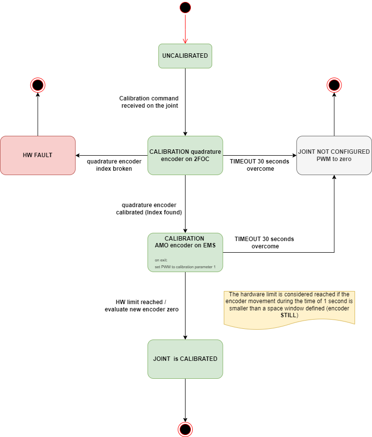
Complete pipeline for the calibration type 10 using AMO encoder at the joint and quadrature encoder at the motor.

As you can see in the above-reported state machine, after the calibration command is received by the EMS, a timer of 30 seconds gets triggered; afterward, we wait until the motor encoder calibration ends; finally, the procedure of the calibration type 10 commences.
The procedure basically consists in moving the slow shaft towards one of the hardware limits as defined in the position set within the calibration parameter calibrationZero. The value of the PWM used is in turn defined through the parameter calibration1. The joint moves until the limit is reached within a time window and within a predefined maximum length, whose values are coded in the firmware.
Finally, if the hard-stop limit position is found before the CALIBRATION TIMEOUT expires, the zero of the AMO encoder is updated with the found offset and the whole calibration completes correctly; otherwise, the joint is moved to the NOT CONFIGURED state, the PWM is set to zero and the motor switched to IDLE.
The FW verifies if the joint has reached the hard position by checking that the encoder position does not change for 1 second, meaning that the relative increase of joint position is smaller than 6.5 deg (1200 iCubDegrees) within 1 second. The encoder position considered for the check is processed to filter out the spikes.