iCub 2.x
iCub 2.x Wiring
- The logic schematics consist of the logical and electrical connections between boards, sensors and motors.
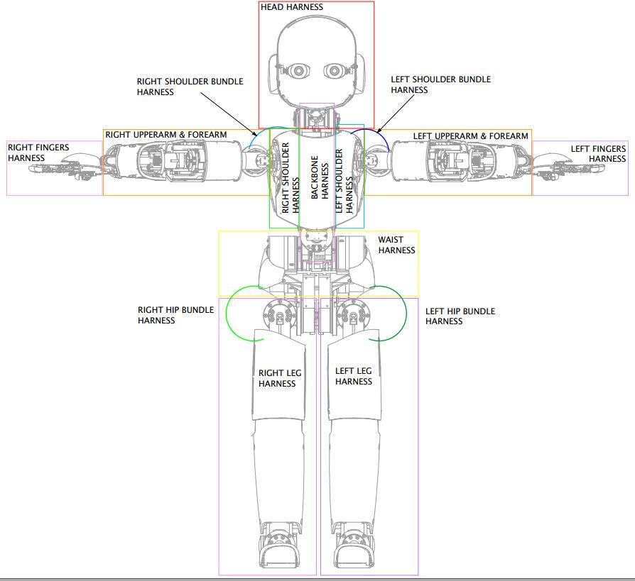
- The harness schematics are the drawings of all the cables and bundles.
- In the image below, you will find the position of all the harnesses that you find in the pdf.
- In order to find a cable in the Harness file of your robot, you should start looking at this picture to find out where you have to look at.
- The Motor&Board_Placement is the document where you can find the wireframe of the robot with all the electronic boards, motors and sensors labels.
ETHERNET backbone
The system architecture of iCub 2.x with ETHERNET backbone is depicted in the following image:
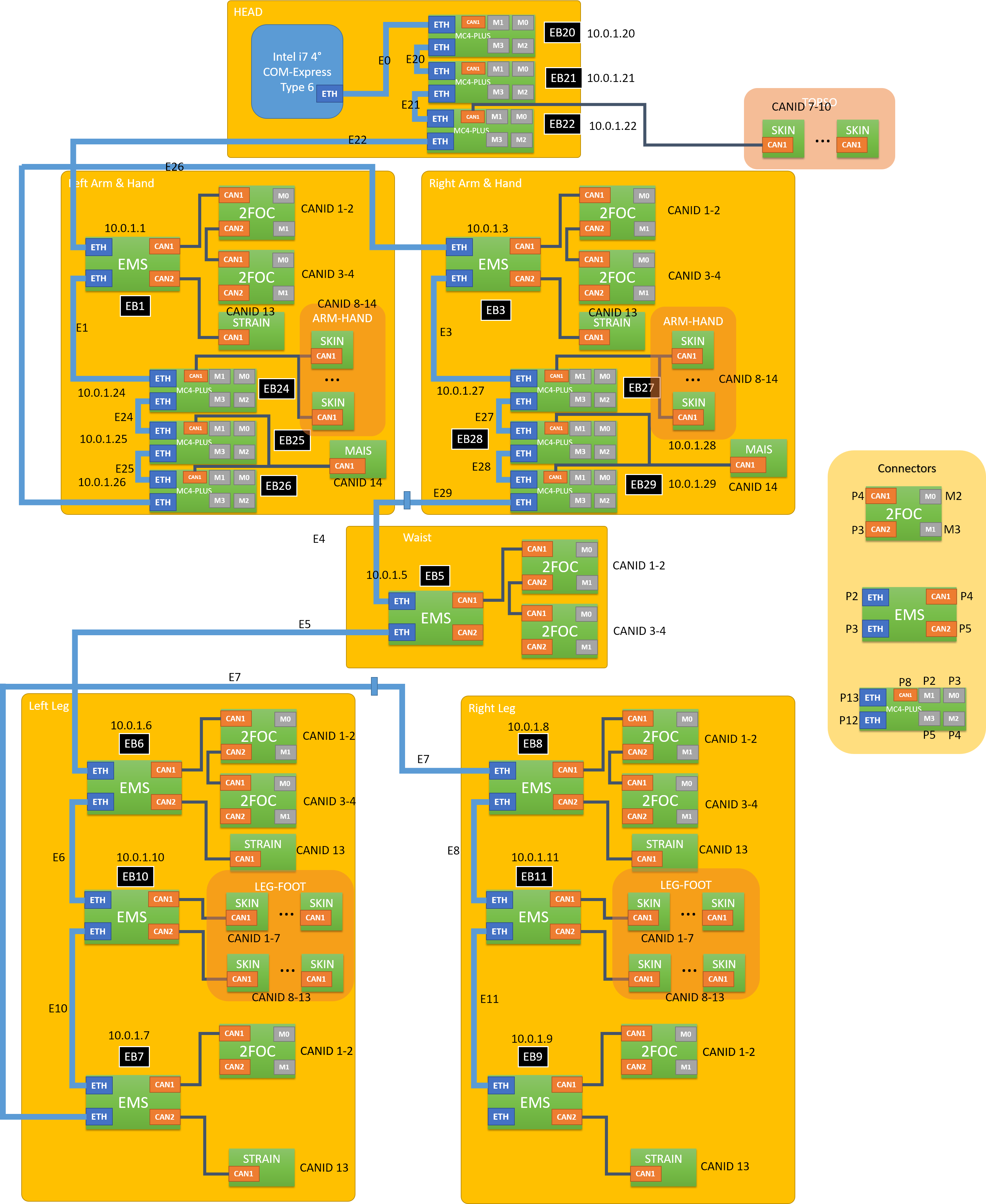
Logic and Harness iCub 2.5-E3.3 (ETH) - Full robot with COM-EXP and MC4-PLUS
Logic and Harness iCub 2.7-E3.6 - Full robot with high performance IMU on the waist and new face expressions
CAN backbone
Logic and Harness iCub 2.x-E2.0.0
Logic and Harness iCub 2.3_E2.3.0 - Full robot with Talking Head
- iCub 2.3 Talking Head Logic
- iCub 2.3 Talking Head Harness
- iCub 2.3 Talking Head Motor and Board Placement