iCub Forward Kinematics - Head
V1
Here's described how to construct the matrices \(T_{RoLe}\) and \(T_{RoRe}\) whose definition is given in ICubForwardKinematics. The matrices are constructed in two steps i.e. \(T_{RoRe} = T_{Ro0} * T_{0n}\) and \(T_{RoLe} = T_{Ro0} * T'_{0n}\). The first matrix \(T_{Ro0}\) describes the rigid roto-translation from the root reference frame to points in the 0th reference frame as defined by the Denavit-Hartenberg convention. In this case \(T_{Ro0}\) is just a rigid rotation which aligns the z-axis with the first joint of the waist. The second matrices $T_{0n} and \(T'_{0n}\) correspond to the Denavit-Hartenberg description of the right and left eye forward kinematic, i.e. the roto-translation from the 0th reference frame to the nth reference frame being n the number of degrees of freedom. The forward kinematic \(T_{0n}\) in this case includes the waist and the right eye forward kinematics. The forward kinematic \(T'_{0n}\) in this case includes the waist and the left eye forward kinematics.
The matrices \(T_{0n}\) and \(T'_{0n}\) are themselves the composition of n matrices as defined by the DH convention: \(T_0n = T_{01} T_{12} ... T_{(n-1)n}\) and \(T'_{0n} = T'_{01} T'_{12} ... T'_{(n-1)n}\). Here is the updated matlab code for computing the forward kinematics with the Denavit Hartenberg notation.
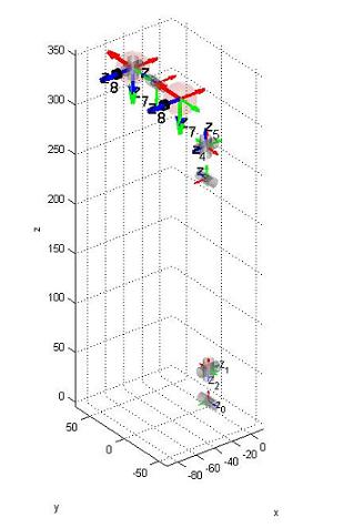
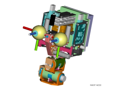
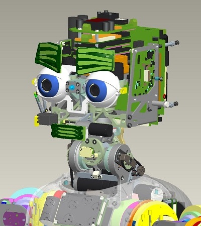
The eyes reference frames are located in the palm as shown in the CAD figure. The \(X\) axis is in red. The \(Y\) axis is in green. The \(Z\) axis is in blue.
 |
 |
Here is the matrix T\_Ro0:
| 0 | -1 | 0 | 0 |
| 0 | 0 | -1 | 0 |
| 1 | 0 | 0 | 0 |
| 0 | 0 | 0 | 1 |
Here is the table of the actual DH parameters which describe \(T_{01}\) ,\(T_{12}\), ... \(T_{(n-1)n}\).
| Link i / H – D | Ai (mm) | d_i (mm) | alpha_i (rad) | theta_i (deg) |
|---|---|---|---|---|
| i = 0 | 32 | 0 | pi/2 | -22 -> 84 |
| i = 1 | 0 | -5.5 | pi/2 | -90 + (-39 -> 39) |
| i = 2 | 2.31 | -193.3 | -pi/2 | -90 + (-59 -> 59) |
| i = 3 | 33 | 0 | pi/2 | 90 + (-40 -> 30) |
| i = 4 | 0 | 1 | -pi/2 | -90 + (-70 -> 60) |
| i = 5 | -54 | 82.5 | -pi/2 | 90 + (-55 -> 55) |
| i = 6 | 0 | 34 | -pi/2 | -35 -> 15 |
| i = 7 | 0 | 0 | pi/2 | -90 + (-50 -> 50) |
Here is the table of the actual DH parameters which describe \(T'_{01}, T'_{12}, ... T'_{(n-1)n}\).
| Link i / H – D | Ai (mm) | d_i (mm) | alpha_i (rad) | theta_i (deg) |
|---|---|---|---|---|
| i = 0 | 32 | 0 | pi/2 | -22 -> 84 |
| i = 1 | 0 | -5.5 | pi/2 | -90 + (-39 -> 39) |
| i = 2 | 2.31 | -193.3 | -pi/2 | -90 + (-59 -> 59) |
| i = 3 | 33 | 0 | pi/2 | 90 + (-40 -> 30) |
| i = 4 | 0 | 1 | -pi/2 | -90 + (-70 -> 60) |
| i = 5 | -54 | 82.5 | -pi/2 | 90 + (-55 -> 55) |
| i = 6 | 0 | -34 | -pi/2 | -35 -> 15 |
| i = 7 | 0 | 0 | pi/2 | -90 + (-50 -> 50) |
Joint Poses (x y z, roll, pitch, yaw) w.r.t. root:
Eyes tilt (G\_sl6) = -62.81 0 340.8 1.57079 0 0
Right Eye (G\_sl7) = -62.81 34 340.8 -3.14159 0 0
Left Eye (Gp\_sl7) = -62.81 -34 340.8 -3.14159 0 0
Right Eye (G\_sl8) = -62.81 34 340.8 0 1.57079 0
Left Eye (Gp\_sl8) = -62.81 -34 340.8 0 1.57079 0
V2
Here's described how to construct the matrices \(T_{RoLe}\) and \(T_{RoRe}\) whose definition is given in ICubForwardKinematics. The matrices are constructed in three steps i.e. \(T_{RoRe} = T_{Ro0} * T_{0n} * T_{nE}\) and \(T_{RoLe} = T_{Ro0} * T'_{0n} * T_{nE}\). The first matrix \(T_{Ro0}\) describes the rigid roto-translation from the root reference frame to points in the 0th reference frame as defined by the Denavit-Hartenberg convention. In this case \(T_{Ro0}\) is just a rigid rotation which aligns the z-axis with the first joint of the waist. The second matrices \(T_{0n}\) and \(T'_{0n}\) correspond to the Denavit-Hartenberg description of the right and left eye forward kinematic, i.e. the roto-translation from the 0th reference frame to the nth reference frame being n the number of degrees of freedom. The forward kinematic \(T_{0n}\) in this case includes the waist and the right eye forward kinematics. The forward kinematic \(T'_{0n}\) in this case includes the waist and the left eye forward kinematics. The last matrix \(T_{nE}\) represents the roto-translation from the nth reference frame to the one placed on the camera sensor.
The matrices \(T_{0n}\) and \(T'_{0n}\) are themselves the composition of n matrices as defined by the DH convention: \(T_{0n} = T_{01} T_{12} ... T_{(n-1)n}\) and $ T'{0n} = T' T'{12} ... T'$. Here is the updated matlab code for computing the forward kinematics with the Denavit Hartenberg notation.
The eyes reference frames are located in the palm as shown in the CAD figure. The \(X\) axis is in red. The \(Y\) axis is in green. The \(Z\) axis is in blue.
|
 |
Here is the matrix \(T_{Ro0}\) :
Here is the table of the actual DH parameters which describe \(T_{01},T_{12}, \dots T_{(n-1)n}\) :
| Link i / H – D | Ai (mm) | d_i (mm) | alpha_i (rad) | theta_i (deg) |
|---|---|---|---|---|
| i = 0 | 32 | 0 | pi/2 | -22 -> 84 |
| i = 1 | 0 | -5.5 | pi/2 | -90 + (-39 -> 39) |
| i = 2 | 0 | -223.3 | -pi/2 | -90 + (-40 -> 22) |
| i = 3 | 9.5 | 0 | pi/2 | 90 + (-20 -> 20) |
| i = 4 | 0 | 0 | -pi/2 | -90 + (-50 -> 50) |
| i = 5 | -50.9 | 82.05 | -pi/2 | 90 + (-30 -> 30) |
| i = 6 | 0 | 34 | -pi/2 | -15 -> 15 |
| i = 7 | 0 | 0 | pi/2 | -90 + (-30 -> 30) |
Here is the table of the actual DH parameters which describe \(T'_{01},T'_{12}, \dots T'_{(n-1)n}\) :
| Link i / H – D | Ai (mm) | d_i (mm) | alpha_i (rad) | theta_i (deg) |
|---|---|---|---|---|
| i = 0 | 32 | 0 | pi/2 | -22 -> 84 |
| i = 1 | 0 | -5.5 | pi/2 | -90 + (-39 -> 39) |
| i = 2 | 0 | -223.3 | -pi/2 | -90 + (-40 -> 22) |
| i = 3 | 9.5 | 0 | pi/2 | 90 + (-20 -> 20) |
| i = 4 | 0 | 0 | -pi/2 | -90 + (-50 -> 50) |
| i = 5 | -50.9 | 82.05 | -pi/2 | 90 + (-30 -> 30) |
| i = 6 | 0 | -34 | -pi/2 | -15 -> 15 |
| i = 7 | 0 | 0 | pi/2 | -90 + (-30 -> 30) |
For both left and right eye, the end-effector matrix \(T_{nE}\) from the last link to the camera sensor is: