BCB Bluetooth Protocol
Introduction
This page describes the Bluetooth communication protocol for the control and diagnostics of the iCub battery backpack system.
The iCub backpack communicates via the BCB electronic board, which embeds a Bluetooth module. To pair with it, no special passwords or codes are needed; the electronic board is always visible from any other device, it is called RNBT-F29x, and must be considered as a SLAVE.
After turned on, when pairing has not yet taken place: - the blue LED DL5 will blink - the green LED DL4 will be on and fixed
both LEDs are next to the Bluetooth module as shown in the following figure:
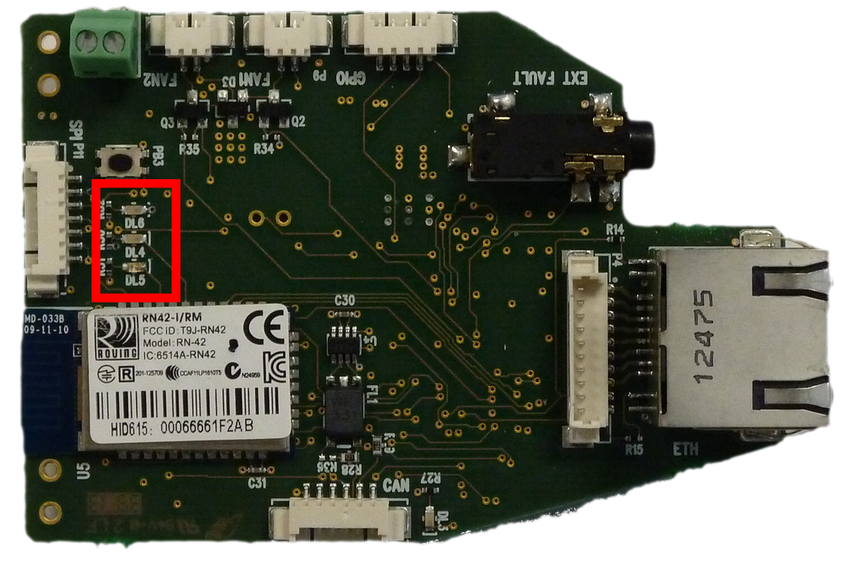
After pairing, the blue LED turns on steadily and the green LED turns off. If there is data transfer in transmission or reception, the orange LED DL6 will flash.
Communication characteristics
Baud rate 115200, 8 data bits, parity none, stop-bit one.
Types of data in transmission and reception
The data transferred through Bluetooth concern the parameters of the iCub battery, system status feedback, sending of commands.
List of commands
Write data
The following table shows the bytes that can be sent and the corresponding function.
| Command | Description |
|---|---|
| 0x00 | Disable data transfer |
| 0x01 | Enable data transfer |
| 0x10 | PC104 power on |
| 0x11 | PC104 shutdown |
| 0x20 | Motors power on |
| 0x21 | Motors shutdown |
| 0xFF | Firmware version of the BCB board |
If data transfer is enabled, the blue led on the card will blink.
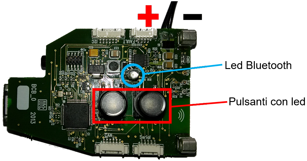
Note: in the event of a fault on the PC104 and/or motors (overcurrent anomaly), the corresponding power supply must be reset using the buttons on the backpack by pressing the flashing red LED button for a few seconds. In any case, investigate or report the problem.
Read data
If data transmission is enabled, the BCB board continuously sends the battery status information (voltage, current, charge), the status of the DC/DC converters (ON, OFF, fault), and the status of the Hot Swap Manager (power good, fault). It also signals a possible restart following a fault.
The string sent is made up of 10 bytes:
| RX[0] | RX[1] | RX[2] | RX[3] | RX[4] | RX[5] | RX[6] | RX[7] | RX[8] | RX[9] |
|---|---|---|---|---|---|---|---|---|---|
| 0x00 | Battery Voltage (MSB) | Battery Voltage (LSB) | Battery current (MSB) | Battery current (LSB) | Battery Charge (MSB) | Battery Charge (LSB) | Backpack Status | \r | \n |
The values of the parameters are obtained as follows:
- \(\text{Battery voltage} = RX[1] \cdot 256 + RX[2] \; \text{expressed in mV}\)
- \(\text{Battery current} = RX[3] \cdot 256 + RX[4] \; \text{expressed in mA}\)
- \(\text{Battery charge} = RX[5] \cdot 256 + RX[6] \; \text{expressed in %}\)
The status byte RX[7] is divided as follows:
| RX[7] (bit 7..0) | Description |
|---|---|
| Bit 7 | 1-> PC104 on, 0-> PC104 off |
| Bit 6 | 1-> PC104 fault , 0-> PC104 ok |
| Bit 5 | 1-> Motors on, 0-> Motors off |
| Bit 4 | 1-> Motors fault , 0-> Motors ok |
| Bit 3 | 1-> HSM on, 0-> HSM off |
| Bit 2 | 1-> HSM running, 0-> HSM not ready yet |
| Bit 1 | 1-> HSM fault, 0-> HSM ok |
| Bit 0 | 1-> restarting after a fault, 0-> normal operation |